1. Wedge Tensile Fixture
Overview
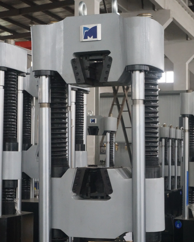
The wedge‑type tensile fixture is designed for reliable gripping of metallic and non‑metallic specimens under increasing tensile load. It utilizes a self‑tightening wedge action: the initial clamping force is low, but as the test force increases, the clamping force automatically increases. This ensures that the specimen is firmly held without slippage, even at high loads.
Key Features
Self‑energizing wedge mechanism – gripping force grows proportionally with the applied tensile load.
Suitable for round and flat specimens with a wide range of cross‑sectional dimensions.
Hardened grip faces provide excellent wear resistance and long service life.
Quick and easy specimen insertion – no special tools required.
Typical Applications
Tensile testing of metals, plastics, composites, and other materials according to ASTM E8, ISO 6892‑1, etc.
High‑force universal testing machines (e.g., hydraulic UTM up to 2000 kN).
Optional: interchangeable grip inserts for different specimen shapes.
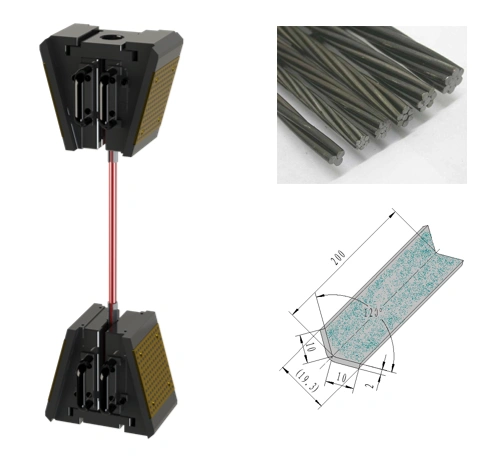
2. Steel Wire Strand Tensile Fixture
Overview
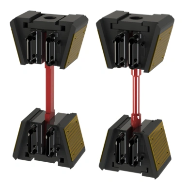
Specifically developed for tensile mechanical property tests of steel wire strands (e.g., prestressing strands, bridge cables). The fixture uses a unique aluminum sheet coated with emery (aluminum oxide) to wrap the sample before clamping. This high‑friction surface effectively prevents force drop and sample slipping, even under maximum test loads.
Key Features
Emery‑coated aluminum wrapping increases friction coefficient between the grip and the strand.
Eliminates the need for expensive, custom‑machined serrated inserts.
Accommodates common strand diameters (e.g., 7.5 mm, 12.7 mm, 15.2 mm).
Designed for extended‑length load frames – strand specimens often exceed 1.2 m in length, and an extended column frame is recommended for proper installation.
Typical Applications
Tensile strength and elongation testing of steel wire strands per ASTM A416, ISO 15630‑3.
Quality control for prestressed concrete reinforcements and bridge cables.
Recommendation: Use with an extended‑height universal testing machine to accommodate long specimen lengths.
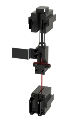
3. Bolt & Nut Fixture
Overview
A comprehensive fixture system for bolt and nut mechanical testing. It is used for bolt wedge load tests, ordinary tensile tests, bolt minimum proof load tests, and nut proof load tests. The system includes abundant threaded fitting connectors, making it adaptable to various bolt sizes and standard threads (metric, inch, etc.).
Key Features
Accepts a wide range of bolt diameters and lengths – easy changeover of adapters.
Wedge‑load testing capability (bolt head wedge angle test) per ISO 898‑1, ASTM F606.
Robust design ensures accurate axial alignment during proof load tests.
High‑strength alloy steel construction for long‑term durability.
Typical Applications
Tensile proof load test of bolts and screws.
Nut guarantee load (proof load) testing.
Bolt wedge tensile test to verify head strength.
Routine quality assurance in fastener manufacturing and construction material testing.
Available with a complete set of threaded adapters for quick configuration.
1. Compression Platen (Compression Platen / Compression Test Platens)
Overview
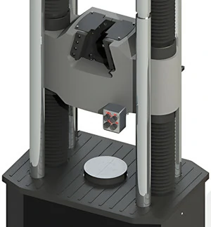
The Compression Platen is a high‑precision accessory designed for material mechanical compression tests on universal testing machines. It features a ball‑end (spherical seating) configuration that ensures axial loading even when the specimen faces are not perfectly parallel. The upper and lower platens are manufactured with high‑hardness surfaces (HRC55‑60) to withstand repetitive high‑force compression cycles without indentation or wear.
Key Features
Spherical seating for automatic alignment – The platen incorporates a spherical surface that self‑levels upon contact with the specimen, guaranteeing true axial force transmission and eliminating bending moments.
High surface hardness (HRC55‑60) – Provides exceptional wear resistance and maintains flatness over thousands of tests.
Scribed lines for specimen positioning – Precision‑etched guide lines on the platen surface allow fast, repeatable centering of cubes, cylinders, or blocks.
Suitable for both static and cyclic compression tests – Robust design suitable for concrete, rock, ceramic, metal, and polymer specimens.
Typical Applications
Compressive strength testing of concrete cubes and cylinders (ASTM C39, EN 12390).
Crush testing of polymer foams, wood, and composite materials.
Determination of yield strength in metals under compression (ASTM E9).
Quality control in construction materials, ceramics, and additive manufacturing parts.
Technical Specifications
Platen hardness: 55–60 HRC
Standard diameters: Ø100 mm, Ø150 mm, Ø200 mm (custom sizes available)
Spherical seating travel: ±3° to compensate for specimen end imperfections
Material: High‑carbon chromium bearing steel, hardened and ground.
Optional accessories: Compression platens with larger diameters, extended column guides for long specimens, and anti‑friction PTFE sheets.
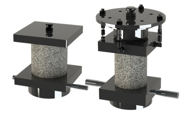
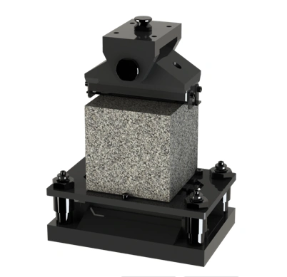
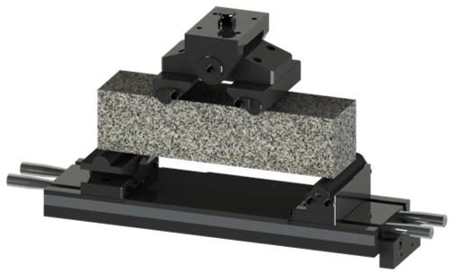
2. Concrete Splitting Fixture (Splitting Tensile Strength Fixture for Concrete Cubes)
Overview
The Concrete Splitting Fixture is specifically designed for the splitting tensile strength test (Brazilian test) of concrete cube specimens. It conforms to international standards such as ASTM C496, BS EN 12390‑6, and ISO 4108. The fixture positions the cube correctly and applies a compressive line load along the central axis, inducing a uniform tensile stress that splits the specimen across the loading plane.
Key Features
Accommodates standard cube sizes – Fits cubes of 100×100×100 mm and 150×150×150 mm (other dimensions available upon request).
Hardened loading strips – Two precision‑ground steel strips (upper and lower) transfer the load evenly along the entire specimen width, preventing premature local crushing.
Self‑centering design – A pivoting upper jaw ensures uniform load distribution even if the cube faces are not perfectly parallel.
Easy specimen insertion and removal – Quick‑release pin or sliding jaw design reduces setup time during high‑throughput testing.
Typical Applications
Determination of splitting tensile strength of concrete (for mix design verification and quality control).
Testing of mortar, plaster, rock cores, and brittle materials where direct tension testing is impractical.
Research and development in concrete admixtures, fiber‑reinforced concrete, and lightweight aggregates.
Technical Specifications
Standard specimen compatibility: 100×100×100 mm & 150×150×150 mm cubes
Loading strip hardness: ≥ 55 HRC
Strip dimensions (width × thickness): 20×10 mm (for 100 mm cube) / 25×15 mm (for 150 mm cube)
Material: Alloy steel with anti‑corrosion coating
Maximum test force: up to 300 kN (higher capacity available)
*Note: The splitting test result (splitting tensile strength) is calculated as: 2P / (π × L × d), where P = maximum load, L = specimen length, d = specimen cross‑section dimension.*
1. Three-Point Bending Fixture
Overview
The Three-Point Bending Fixture is engineered for flexural performance testing of metallic materials according to ASTM E290, ISO 7438, and similar standards. It features a robust support base with hardened rollers that minimize unnecessary load and friction on the specimen, thereby ensuring highly accurate test results. The roller span is adjustable, and the base is equipped with a clear scale for precise positioning.
Key Features
Hardened support rollers – High‑durability rollers reduce frictional losses and prevent indentation, improving measurement repeatability.
Adjustable span – The distance between the lower support rollers can be easily modified via a scale‑marked base, accommodating different specimen lengths and bending requirements.
Standard roller width 125 mm – Suitable for most metal beam and bar specimens; wider rollers available on request for larger samples.
Easy specimen alignment – The fixture allows fast centering of the specimen under the upper loading roller.
Typical Applications
Bend testing of metal bars, rods, plates, and welded joints (qualification of ductility).
Determination of flexural strength, modulus of rupture, and bend angle for quality control.
Aerospace, automotive, and construction material testing.
Technical Specifications
Roller span adjustable range: 20 – 300 mm (depending on base length)
Standard roller width: 125 mm (custom widths available)
Roller material: Bearing steel, hardened to ≥ 58 HRC
Maximum force capacity: up to 250 kN (compatible with hydraulic UTMs)
Scale resolution: 1 mm
Optional: Custom bending center size, extended span lengths, and interchangeable roller diameters.
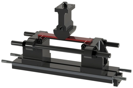
2. Four-Point Bending Fixture
Overview
Designed specifically for measuring the flexural strength (modulus of rupture) of concrete and other brittle materials, the Four-Point Bending Fixture conforms to ASTM C78, EN 12390-5, and ISO 4012. The fixture includes two upper loading rollers and two lower support rollers; the distance between both upper and lower rollers can be adjusted according to the specimen length, providing a pure bending zone without shear forces.
Key Features
Adjustable loading and support spans – Independent adjustment of the upper (loading) roller spacing and lower (support) roller spacing to suit different specimen lengths and loading configurations.
Standard specimen compatibility – Accepts concrete beams of 100×100×400 mm and 150×150×600 mm (other sizes upon request).
Hardened steel rollers – Ensure durability and reduce friction, maintaining accurate load transfer.
Self‑centering design – The upper assembly pivots to evenly distribute load across the two loading rollers.
Typical Applications
Flexural strength testing of concrete beams for pavement, bridge decks, and structural elements.
Quality control of fiber‑reinforced concrete, mortar, and ceramic tiles.
Research and development for construction materials.
Technical Specifications
Standard beam sizes: 100×100×400 mm / 150×150×600 mm
Lower support span adjustable: 300 – 500 mm (for 400 mm beam) / 450 – 700 mm (for 600 mm beam)
Upper loading span: typically 1/3 of lower span (adjustable)
Roller diameter: 25 – 38 mm (option for larger diameters)
Maximum force: up to 100 kN
Note: Four‑point bending eliminates shear forces in the middle third of the specimen, providing a pure flexural test mode.
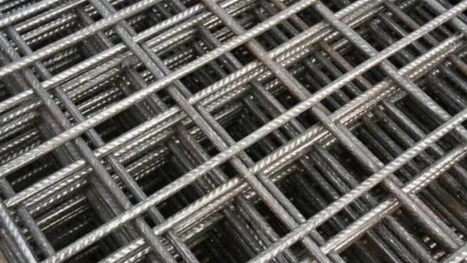
3. Welded Steel Fabric Shear Fixture
Overview
The Welded Steel Fabric Shear Fixture is purpose‑built for the tensile shear test of welded steel fabric (also known as welded wire mesh). It securely fixes the specimen – typically a cruciform or lap‑shear sample cut from the fabric – while the hydraulic system of the universal testing machine applies axial tension. This fixture is essential for evaluating the shear strength of welded intersections.
Key Features
Robust specimen clamping – Special grips hold the welded steel fabric without slipping, ensuring the weld point is aligned with the load axis.
Hydraulic axial loading compatibility – Designed for use with hydraulic universal testing machines, delivering high shear forces up to 1000 kN.
Conforms to ASTM A185/A497 – Meets international standards for welded wire mesh shear testing.
Quick‑change adapters – Allows rapid switching between different wire diameters and grid spacings.
Typical Applications
Shear strength verification of welded intersections in concrete reinforcement mesh.
Quality assurance for welded steel fabric used in slabs, walls, and precast elements.
Research on weld quality and material ductility.
Technical Specifications
Maximum test load: 1000 kN (higher capacities available)
Specimen types: lap‑shear and cross‑shaped samples from welded fabric
Grip opening range: up to 20 mm (covers typical wire diameters 4 – 12 mm)
Compliance: ASTM A185, A497, BS 4483
Important: Always use safety shielding when testing welded fabric due to potential sudden fracture.
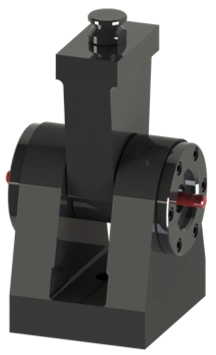
4. Double-Sided Shear Fixture (Double‑Sided Compression Shear Fixture)
Overview
The Double‑Sided Shear Fixture is designed for double‑sided compression shear testing of metallic samples. The fixture is supported at both ends, creating a well‑defined shear plane through the specimen. It is particularly suitable for determining the shear strength of sheet metals, rods, and other components where a pure shear failure mode is required.
Key Features
Both‑end support design – Provides stable, symmetrical loading and prevents bending moments during testing.
Convenient and reliable installation – The fixture slides easily into the UTM compression space with alignment pins for repeatable positioning.
Hardened shear anvils – Wear‑resistant anvils maintain sharp edges, ensuring clean shear fractures.
Compatible with various specimen geometries – Accepts round bars, square bars, and flat plates.
Typical Applications
Shear strength testing of metallic materials per ASTM B769, ISO 8740.
Quality control of fasteners, pins, rivets, and sheet metal components.
Failure analysis and material specification verification.
Technical Specifications
Maximum test force: 100 – 600 kN (depending on model)
Specimen diameter range: 3 – 25 mm (for round bars)
Plate thickness: up to 15 mm
Material: Hardened tool steel (58–62 HRC)
Weight: approximately 15 – 40 kg
Optional: Replaceable shear anvils for different specimen sizes and extended‑height models for larger samples.
1. Safety Enclosure (Protective Enclosure for UTM)
Overview
The Safety Enclosure is a floor‑mounted, three‑sided protective structure constructed from an aluminium profile frame and transparent acrylic panels. It is designed to prevent splashing, flying fragments, or sudden ejection of test specimens during destructive testing. By creating a secure physical barrier around the testing area, the enclosure ensures a safe operating zone for personnel while allowing clear visual observation of the test in progress.
Key Features
Three‑sided protection – Front, left, and right sides covered; the open back facilitates easy specimen loading and fixture changes.
High‑impact acrylic panels – Transparent, shatter‑resistant material provides excellent visibility while containing debris.
Floor‑mounted, rigid frame – Aluminium profile construction offers lightweight strength and corrosion resistance; can be bolted to the laboratory floor for added stability.
Optional interlock system – Doors equipped with safety switches that automatically stop the test if opened, complying with machinery safety directives (e.g., EN 953, ISO 13857).
Typical Applications
Universal testing machines (hydraulic and electromechanical) used for tensile, compression, bending, and shear tests on metals, composites, and brittle materials.
High‑force destructive testing where sudden specimen fracture may cause projectile hazards.
Laboratories requiring compliance with occupational safety regulations (OSHA, EU Machinery Directive).
Technical Specifications
| Parameter | Value |
|---|---|
| Frame material | Aluminium alloy (6063) |
| Panel material | Acrylic (PMMA), 8–12 mm thickness |
| Protection coverage | Left, right, front (three sides) |
| Mounting | Floor‑standing with adjustable feet |
| Optional interlock | Magnetic / limit switch, 24V DC |
| Customizable dimensions | Yes (width, height, depth tailored to UTM frame) |
Option: Add an automatic sliding door or a rear mesh panel for increased ventilation.
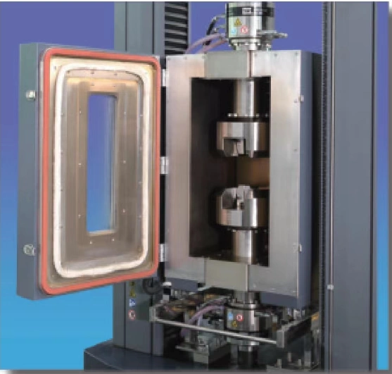
2. Environmental Chamber (–196°C to +350°C)
Overview
The Environmental Chamber is a temperature‑controlled enclosure that fits directly around the test space of a universal testing machine. It enables mechanical property testing (tensile, compression, bending) under precisely controlled sub‑ambient and elevated temperatures. With a wide temperature range from –196°C (liquid nitrogen cooled) to +350°C (electric heating), this chamber is ideal for materials that must perform in extreme environments, such as aerospace alloys, polymers, and composites.
Key Features
Wide temperature range – Covers cryogenic (–196°C) via LN₂ injection up to +350°C with electrical heating elements.
Uniform temperature distribution – Integrated circulation fan and baffle ensure ±2°C uniformity across the test zone.
Compatible with multiple fixture types – Designed to accommodate tensile grips, compression platens, and bending fixtures without disassembly.
Integrated pass‑through ports – Allow connection of extensometer arms, thermocouples, or cooling lines while maintaining thermal seal.
Touchscreen controller – Programmable ramp/soak profiles, data logging, and over‑temperature protection.
Typical Applications
Low‑temperature impact and tensile testing of plastics, rubber, and composites (ASTM D638, ISO 527).
High‑temperature tensile/creep testing of metals and superalloys (ASTM E21, ISO 6892‑2).
Thermal cycling and durability tests on electronic components, adhesives, and seals.
Technical Specifications
| Parameter | Value |
|---|---|
| Temperature range | –196°C ~ +350°C |
| Cooling method | Liquid nitrogen (LN₂) injection |
| Heating method | Electric resistance heaters (stainless steel sheathed) |
| Temperature uniformity | ±2°C (over full range) |
| Control accuracy | ±0.5°C |
| Internal working space (W×D×H) | Customizable (typically 300×250×500 mm to 600×500×1000 mm) |
| Controller | 7″ HMI touchscreen with ramp/soak programming |
Note: For tests requiring sub‑zero temperatures without LN₂, optional mechanical refrigeration (to –70°C) is available.
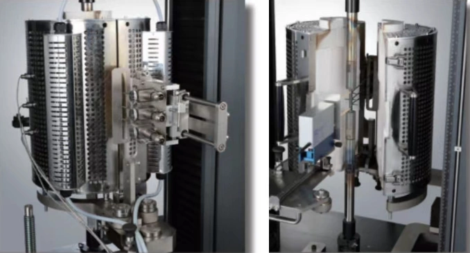
3. Atmospheric Furnace (300°C to 1200°C)
Overview
The Atmospheric Furnace is a high‑temperature testing accessory designed for mechanical property evaluation of materials at extreme elevated temperatures. Operating from 300°C up to 1200°C, this furnace is ideal for metals, ceramics, and advanced composites that must withstand high‑service‑temperature environments. It wraps around the specimen and pull rods of the universal testing machine, providing a uniform hot zone while allowing tensile, compression, or bending tests to be performed.
Key Features
High maximum temperature 1200°C – Suitable for superalloys, refractory metals, and ceramic matrix composites.
Three‑zone heating – Independent top, middle, and bottom zones ensure superior temperature uniformity (±3°C) over the specimen gauge length.
Fast heating and cooling – Silicon carbide (SiC) or Kanthal heating elements enable rapid ramp rates (up to 20°C/min).
Integrated viewport – Quartz window allows optical extensometer or video camera observation of the specimen.
Gas‑tight construction – Can be purged with inert gas (argon, nitrogen) to prevent oxidation of sensitive materials.
Typical Applications
High‑temperature tensile testing of steels, nickel‑based alloys (Inconel, Hastelloy) per ASTM E21, ISO 6892‑2.
Creep and stress‑rupture testing at elevated temperatures.
Compression testing of ceramics and refractory bricks.
Research on thermal barrier coatings and additive‑manufactured metals.
Technical Specifications
| Parameter | Value |
|---|---|
| Temperature range | 300°C ~ 1200°C (optional 1400°C available) |
| Heating elements | Kanthal A‑1 (FeCrAl) or SiC |
| Number of zones | 3 (independent control) |
| Uniformity | ±3°C over 100 mm length (at 1000°C) |
| Heating rate | 5 – 20°C/min (programmable) |
| Furnace inner bore | Typically 60 – 100 mm diameter |
| Specimen grip extension | Custom pull rods made of high‑temperature alloy (e.g., Inconel 718) |
| Power supply | 380V, three‑phase, 50/60 Hz |
Important: Always use high‑temperature grips and extensometer arms designed for furnace operation. Optional water‑cooled grips extend the life of the pull rods.
Extensometers
Accurate strain and displacement measurement is critical for material mechanical property tests. Our range of extensometers provides reliable, high‑precision solutions for various specimens, temperatures, and testing standards. All models are compatible with universal testing machines (UTMs) and can be seamlessly integrated into your test workflow.
Contact Extensometer
Contact extensometers physically attach to the specimen and directly measure axial or circumferential deformation. They offer excellent accuracy, high resolution, and are suitable for static and dynamic tests. The following types are available:
Axial Extensometer
Designed for measuring longitudinal strain in tensile, compression, and bend tests. The axial extensometer features a low‑mass arm system that follows specimen elongation without slippage. Typical gauge lengths cover most standard specimens, and the device can be easily mounted with spring‑loaded arms or quick‑fit bands.
Circumferential Extensometer
Specifically developed for measuring transverse strain (e.g., diameter change) in compression or tensile tests, such as determination of Poisson’s ratio or expansion of ring specimens. The circumferential extensometer wraps around the specimen circumference and provides continuous, high‑linearity output.
High Temperature Extensometer
Suitable for tests performed inside an environmental chamber or furnace. The high‑temperature extensometer uses ceramic rods or extension arms that transfer specimen deformation to sensors located outside the hot zone. This design ensures stable measurement under elevated temperatures while protecting sensitive electronics.
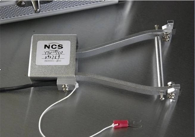
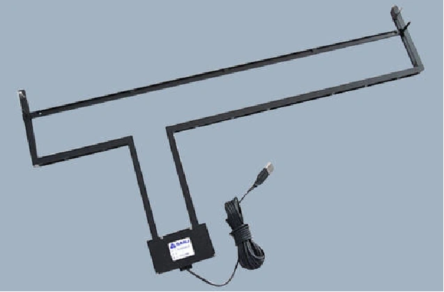
Long Gauge Length Extensometer (for Wire Strand)
Engineered for testing steel wire strands, cables, and other long or coarse‑grained materials where a conventional short gauge length is insufficient. The long gauge length extensometer covers a larger portion of the strand, delivering representative strain data and minimizing the influence of individual wire slip. It is the preferred solution for strand tensile tests according to industry standards.
Common applications for contact extensometers
Tensile modulus and yield point determination (metals, plastics, composites)
Poisson’s ratio measurement (axial + circumferential combination)
High‑temperature testing (up to furnace capabilities)
Wire strand and rope elongation tests
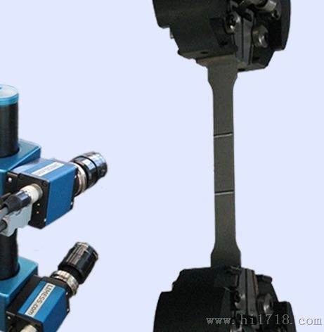
Video Extensometer (Non‑contact Extensometer)
The Video Extensometer is a non‑contact strain measurement system based on a high‑resolution digital camera and real‑time image processing algorithms. During the test, the camera continuously captures images of the specimen surface (often aided by high‑contrast marks or speckle patterns). The software tracks the displacement of these features, dynamically measuring strain and displacement without physically touching the specimen.
Key advantages
Non‑contact operation – no influence on specimen behavior, ideal for soft or delicate materials.
Suitable for large deformation, including necking and elongation to break.
Works with a wide range of specimen geometries and materials (metals, plastics, elastomers, textiles).
No knife edges or arms to clean or replace – reduces maintenance.
Typical applications
Tensile testing of films, foils, and elastomers (ASTM D412, ISO 37).
High‑elongation materials where contact extensometers might slip or damage the specimen.
Dynamic tests requiring high‑speed data capture.
Quality control in production environments (fast set‑up).
The video extensometer can be used as a standalone device or integrated with the UTM controller for synchronized test data.
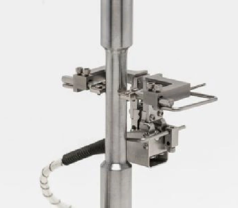
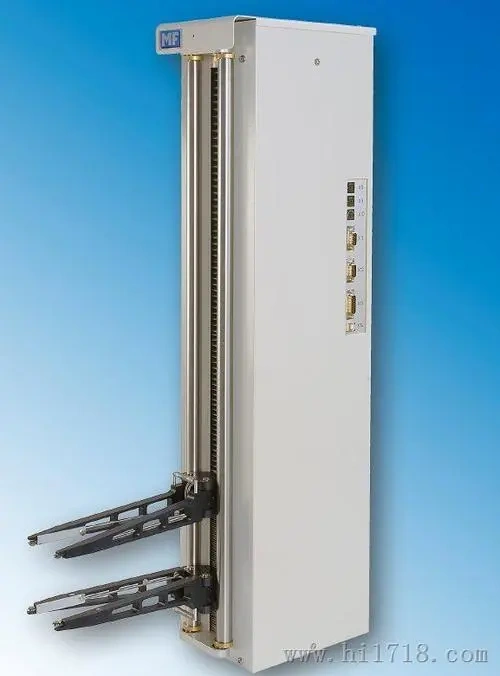
Automatic Extensometer
The Automatic Extensometer is a fully motorized contact extensometer designed for unattended, high‑throughput testing. It automatically clamps onto the specimen at the start of the test and releases after specimen failure, eliminating manual attachment and removal. The device is typically integrated into an automated testing line or a robotic system.
Key features
Automatic specimen sensing and clamping – no operator intervention required.
Programmable gauge length and clamping force.
Compatible with axial and some diametral measurements.
Reduces test cycle time and operator variability.
Seamless integration with UTM software for batch testing.
Typical applications
High‑volume production testing (e.g., rebar, wire, fasteners).
Laboratory automation and unmanned shift operation.
Ensuring consistent specimen alignment and grip pressure across hundreds of tests.