What is Creep Test?
Creep test is a material mechanical property test that measures the slow plastic deformation phenomenon of metal materials under long-term constant temperature and constant stress. The higher the temperature or stress, the more significant the creep phenomenon. Creep can occur under a single stress (tension, compression, or torsion) or under composite stress. The usual creep test is conducted under uniaxial tensile conditions. In terms of stress rupture test, a differentiation is made between short term tests up to approximately 10,000 hours and long term tests starting at approximately 10,000 hours.
What is typical creep curve?
Discovery of creep
In 1905, F. Philips of England first observed the phenomenon of metal wire creep. In 1910, the E.N.da C. Andrade experiment in England confirmed that several pure metals had the same creep characteristics. After Dickenson published the creep test results of steel in 1922, it was recognized that metal components bearing at high temperatures would creep, even though the stress they were subjected to was much lower than the yield strength of the component material at that temperature. The study of creep testing has been given more attention since then. After the 1920s, high-temperature and high-pressure technology developed rapidly, and creep testing has become one of the main performance tests that must be conducted on high-temperature metal materials (see high-temperature alloys). In creep testing, the relationship between deformation and time is represented by the creep curve.
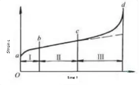
The criterion (index) for metal creep resistance is the creep limit, which refers to the stress that causes the specimen to produce a specified creep rate in the second stage of creep at a certain temperature, or the stress that causes the specimen to produce a specified elongation rate at a certain temperature and a specified time interval. The creep limit measured by creep rate and the creep limit measured by elongation are shown in Figure 1, respectively. The symbol I on σ here represents the test temperature (℃), II represents the specified creep rate (%/hour), III represents the specified elongation rate (%), and IV represents the specified test duration (hours). For example (Figure 2), the creep limit at an allowable elongation of 0.2% after 100 hours of testing at a temperature of 600 ℃.
According to the general empirical formula, the second stage creep rate is linearly related to the logarithm of stress when the temperature remains constant. Based on this, the creep limit can be calculated using interpolation or extrapolation methods. However, due to surface oxidation or erosion of the sample, as well as changes in internal organizational structure, this linear relationship may no longer exist over a long period of time. Therefore, when obtaining long-term data from short-term creep limit data, it is generally only possible to extrapolate by one order of magnitude over time. When using creep data for temperature and time extrapolation, the Larson Miller parameter method is usually used.
For certain components that are only allowed to undergo a certain amount of deformation during long-term high-temperature operation, such as power plant boilers and steam turbines, creep limit is an important design basis. Most regulations stipulate that a creep rate of 10 to the power of 5 (%/hour) is equivalent to a deformation of 1% after 100000 hours. The metal materials used to manufacture such components typically require tens of thousands or even longer hours of creep testing.
There are many factors that affect the results of creep tests, among which the most important are the long-term stability of temperature control, deformation measurement accuracy, and specimen processing technology.
ASTM E139-11 Standard Test Methods for Conducting Creep, Creep-Rupture, and Stress-Rupture Tests of Metallic Materials
These test methods cover the determination of the amount of deformation as a function of time (creep test) and the measurement of the time for fracture to occur when sufficient force is present (rupture test) for materials when under constant tensile forces at constant temperature. It also includes the essential requirements for testing equipment. For information of assistance in determining the desirable number and duration of tests, reference should be made to the product specification
This standard defines the measurement process of creep rate, which is divided into initial strain rate, steady-state creep rate, and three-stage creep, providing a unified technical language for material development and process validation.
The key contents covered by the standard include:
Sample specifications and preparation requirements
Loading and temperature control methods
Stress and strain measurement standards
Principles of Data Collection and Curve Drawing
Definition of endurance time and strength limit
Referenced ASTM Standards
E4 Practices for Force Verification of Testing Machines
E6 Terminology Relating to Methods of Mechanical Testing
E8/E8M Test Methods for Tension Testing of Metallic Materials
E21 Test Methods for Elevated Temperature Tension Tests of Metallic Materials
E29 Practice for Using Significant Digits in Test Data to Determine Conformance with Specifications
E74 Practices for Calibration and Verification for Force-Measuring Instruments
E83 Practice for Verification and Classification of Extensometer Systems
E177 Practice for Use of the Terms Precision and Bias in ASTM Test Methods
E220 Test Method for Calibration of Thermocouples By Comparison Techniques
E292 Test Methods for Conducting Time-for-Rupture Notch Tension Tests of Materials
E633 Guide for Use of Thermocouples in Creep and Stress-Rupture Testing to 1800°F (1000°C) in Air
E1012 Practice for Verification of Testing Frame and Specimen Alignment Under Tensile and Compressive Axial Force Application
Related standards for metal creep tests
ISO 204 Metallic materials – Uniaxial creep testing in tension
ASTM E139 Standard Test Methods for Conducting Creep, Creep-Rupture, and Stress-Rupture Tests of Metallic Materials
EN 2002-005 Test method for metallic material– Part 005: Uninterrupted creep and stress-rupture testing
ASTM E328 Standard Test Methods for Stress Relaxation for Materials and Structures
ISO 15630-3 Steel for the reinforcement and prestressing of concrete – Test methods
ASTM G129 Standard Practice for Slow Strain Rate Testing to Evaluate the Susceptibility of Metallic Materials to Environmentally Assisted Cracking
ASTM F519 Standard Test Method for Mechanical Hydrogen Embrittlement Evaluation of Plating/Coating Processes and Service Environments
ASTM F1624 Standard Test Method for Measurement of Hydrogen Embrittlement Threshold in Steel by the Incremental Step Loading Technique
ASTM E1457 Standard Test Method for Measurement of Creep Crack Growth Times in Metals
ASTM E2760 Standard Test Method for Creep-Fatigue Crack Growth Testing
ASTM E647 Standard Test Method for Measurement of Fatigue Crack Growth Rates
ASTM E2714 Standard Test Method for Creep-Fatigue Testing
ASTM E606 Standard Test Method for Strain-Controlled Fatigue Testing
ISO 12106 Metallic materials – Fatigue testing – Axial-strain-controlled method
Validated Code-of-Practice for Strain-Controlled Thermo-Mechanical Fatigue Testing
ISO 12111 Metallic materials – Fatigue testing – Strain-controlled thermomechanical fatigue testing method
ASTM E2368 Standard Practice for Strain Controlled Thermomechanical Fatigue Testing
Creep Rupture Test
The criterion for creep fracture resistance is the ultimate strength limit, which refers to the maximum stress that does not cause fracture at a certain temperature and within a specified time. For some components that do not consider deformation and only consider service life during high-temperature operation, the ultimate strength limit is an important design basis.
The endurance strength test is similar to the creep test, but only determines the fracture time of the specimen during the test process. The morphology of the fracture surface of the sample varies depending on the test conditions, and it mostly fractures along the grain boundary under high temperature and low stress. According to the general empirical formula, when the temperature remains constant, the logarithm of the fracture time and stress is linearly related. Based on this, the endurance strength limit can be calculated using interpolation or extrapolation methods. To ensure the reliability of extrapolation results, the extrapolation time should generally not exceed 10 times the test time.
The elongation and cross-sectional shrinkage after fracture are used to characterize the persistent plasticity of metals. If the persistent plasticity is too low, the material will undergo brittle fracture during use. The persistent strength notch sensitivity qg is expressed as the ratio of the persistent strength limits of notched specimens and smooth specimens under the same fracture conditions. When the sensitivity of the gap is too high, metal materials often break prematurely during use. Both persistent plasticity and persistent strength notch sensitivity are important performance criteria for high-temperature metal materials.
The endurance strength test is usually conducted at a constant temperature and load. In recent years, some laboratories in various countries have developed temperature and load endurance strength testing methods, which have opened up new avenues for testing the endurance strength performance of components under conditions close to use.
Stress Relaxation Test
Under the condition of constant total deformation of metal components, the process of continuously reducing stress due to the transition from elastic deformation to plastic deformation is called stress relaxation. This phenomenon often occurs in springs, bolts, and other pressure fittings, especially at high temperatures. Therefore, stress relaxation tests are usually conducted at high temperatures. The duration of the first stage of the curve is relatively short, and the stress decreases sharply with time. The second stage lasts longer and tends to be constant. Usually, the residual stress after a specified time is used as the criterion for metal stress relaxation resistance.
The stress relaxation test can be used to determine the initial stress required for bolted joints to maintain sufficient fastening force during long-term use at high temperatures, predict the reduction of sealing gasket sealing, spring elasticity, stability of steel bars in prestressed concrete, and determine the heat treatment conditions required for forgings, castings, and welded parts to eliminate residual stress. For metal materials used as fasteners, stress relaxation tests are often conducted at different temperatures and initial stresses to gain a comprehensive understanding of their performance. The experimental conditions have a significant impact on the stress relaxation test results. The key to ensuring good reproducibility of experimental results is to control the constancy of the total variable and the stability of temperature.
Environment:
The device and method for heating the sample should provide necessary temperature control to meet the requirements specified below, and do not require more frequent manual adjustments than once every 24 hours after applying the load.
Up to 1800 ℉ (1000 ℃) and below: ± 3 ℉ (2 ℃)
Above 1800 ℉ (1000 ℃): ± 5 ℉ (3 ℃)
Unless otherwise agreed in advance, the sample should be heated in air using a resistance furnace or radiation furnace at atmospheric pressure.
When the length of the parallel segment is less than 2 inches (50 mm), at least two thermocouples should be connected to the specimen, one near each end of the parallel segment. For parallel length segments of 2 inches or longer, add a third thermocouple near the center.
Test procedure:
Sample preparation: Prepare standard size specimens according to ASTM E139 requirements, ensuring that the surface of the specimens is free of mechanical damage and defects.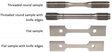
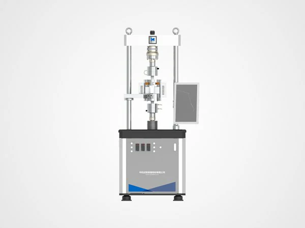
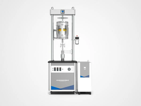
Equipment verification: Use SINOTEST RDL series electronic creep testing machine to ensure the accuracy of the loading device and temperature control system.

RDJ Series Mechanical Creep testing system
RDJ mechanical creep endurance testing system
▪Capacity:
RDJ-10:10kN
RDJ-30:30kN
RDJ-50:50kN
RDJ-100:100kN
▪Knife bearing structure
▪PID temperature control
▪Three stage heating
▪Break point recovery, offline test
RPL Series Creep-Fatigue testing system
RPL series of high temperature electronic creep fatigue testing system
▪Capacity:
RPL-10:10kN
RPL-30:30kN
RPL-50:50kN
RPL-100:100kN
▪Electromechanical servo drive
▪PID temperature control
▪Three stage heating
▪Break point recovery, offline test
RDL Series Creep-Fatigue testing system
RDL series electronic creep durability testing system
▪Capacity:
RDL-10:10kN
RDL-30:30kN
RDL-50:50kN
RDL-100:100kN
▪Electromechanical servo drive
▪PID temperature control
▪Three stage heating
▪Break point recovery, offline test
Temperature uniformity detection: Temperature sensors are arranged at multiple points inside the furnace to ensure uniform heating of the sample and temperature fluctuations of less than ± 2 ℃.
Loading: Load according to the designed stress level and maintain a constant load environment.
Data collection: Real time collection of sample deformation data, intelligent processing to obtain strain time relationship curves.
Curve analysis: Determine the steady-state creep rate region, evaluate the creep stage and fracture time limit.
Report preparation: Based on industry parameters and customer needs, provide a detailed testing report
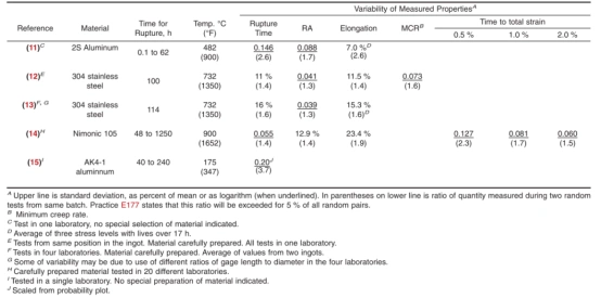
Variability of Measured Properties