Based on years of experience in the R&D and manufacturing of testing machines, **Sinotest Equipment Co., Ltd.** has proposed the **Four-Point Direct Deformation Measurement Method**. This method is mainly applicable to the overall stiffness measurement of confining pressure triaxial testing machines and true triaxial testing machines. The basic principle of this method is: By directly measuring the deformation data of the frame when the rock triaxial testing machine applies the maximum load to the specimen, the actual stiffness value can be obtained by substituting the measured deformation data and force value into the formula. The Four-Point Direct Deformation Measurement Method generally involves the following steps to measure the stiffness of a triaxial testing machine:
(1)First, preheat the testing machine and the control & data acquisition system;
(2) After installing the metal specimen fixture, perform **3 cycles of full loading and unloading**;
(3) Prepare 4 dial gauges (or 4 deformation sensors) and select four test points in a **cross-shaped distribution** as shown in the figure below. The test points should be positioned as close to the loading center as possible.
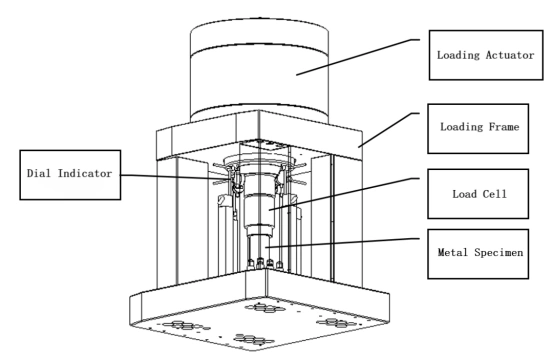
Figure 2: Schematic Diagram of Stiffness Measurement
(4) Measure the frame deformation with dial gauges under the maximum load condition. Repeat the measurement at each point at least 3 times and take the average value. (If simultaneous measurement at all 4 points is not possible, the measurement may be performed in 4 separate times, but a testing machine shall be tested at no fewer than 4 points in total.)
(5) Calculate the stiffness value using the stiffness calculation formula provided above. The acceptance criterion is that the stiffness value at each test point meets the specified stiffness requirements.
We conducted stiffness testing on three typical triaxial testing machines equipped with conventional frames from Sinotest, using the Four-Point Direct Deformation Measurement Method.Their technical parameters, testing procedures and measurement results are presented below, which verifies the feasibility of applying this method to actual production.
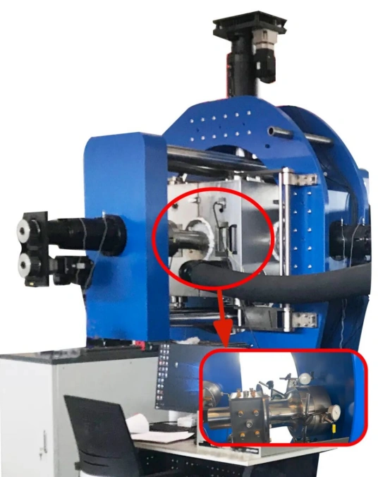
Rock True Triaxial Testing Machine
ZSZ-3000
Frame Type: Column-type Gantry Frame
Technical Specifications
Maximum Loading Capacity:Compression: 1000 kN (X/Y axes), 3000 kN (Z axis);
Force Measurement Accuracy: ≤ ±0.5% of indicated value;
Main Frame Stiffness: ≥ 10 GN/m.
Stiffness Test Procedure:

Stiffness Test Results:
X-axis stiffness: 25 GN/m
Y-axis stiffness: 25 GN/m
Z-axis stiffness: 14.28 GN/m
Result Analysis: The stiffness of each axis exceeds 10 GN/m, which meets the technical specifications.
Asphalt Pavement Material True Triaxial Testing Machine
ZSZ-200
Frame Type:Four-column and assembled combined frame
Technical Specifications:
Maximum Loading Capacity:Horizontal X/Y axes: ±100 kN;Vertical Z axis: ±200 kN;
Maximum Dynamic Frequency: 25 Hz;
Force Measurement Accuracy: ≤ ±0.5% of indicated value;
Main Frame Stiffness: ≥ 1 GN/m.
Stiffness Test Procedure:
Stiffness Test Results X-axis stiffness: 1.1 GN/m
- X-axis stiffness: 1.0 GN/m
- Y-axis stiffness: 1.1 GN/m
Result Analysis: The stiffness of each axis exceeds 1 GN/m, meeting the technical specification requirements.
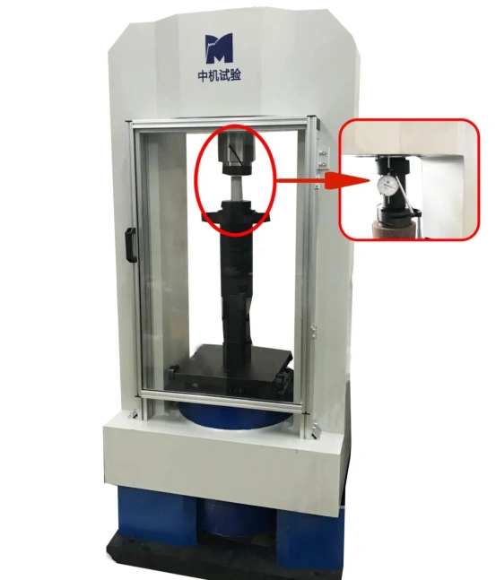
Confining Pressure Triaxial Testing Machine
YSS-2000
Frame Type:Integrated Rectangular Frame
Technical Specifications:
Maximum Loading Capacity:Vertical Z-axis compression: 2000 kN
Confining Pressure: 100 MPa
Force Measurement Accuracy: ≤ ±0.5% of indicated value
Main Frame Stiffness: ≥ 10 GN/m
Stiffness Test Procedure:
Stiffness Test Results Z-axis stiffness: 10.52 GN/m
Result Analysis: The stiffness of each axis exceeds 1 GN/m, meeting the technical specification requirements.