ASTM D695 provides a waisted specimen geometry for unreinforced and reinforced plastics with a thickness of < 3.2 mm, with which the compressive modulus (when using suitable strain measurement system) and compressive strength can be determined in a test. An additional support jig must be used for this.
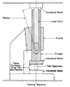
NOTE: Devices similar to the one illustrated have been successfully used in a number of different laboratories. Details of the device developed at the National Institute for Standards and Technology are given in the paper by Aitchinson, C. S., and Miller, J. A., “A Subpress for Compressive Tests,” National Advisory Committee for Aeronautics, Technical Note No. 912, 1943.
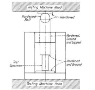
ASTM D695 requires a support jig for the specimen when testing materials with a thickness < 3.2 mm. The supported specimen is then placed in a suitable compression fixture (also referred to as a subpress or compression tool in ASTM D695).
This kind of end loading compression fixture is also referred to as modified ASTM D695 device in the Boeing BSS 7260 standard.
The test standards DIN EN 2850 Method B and SACMA SRM-1R-94 also use this principle, with minor differences in the dimensions of the support jig and the specimens.
It should be noted that the length of the support jig according to DIN EN 2850 Method B is defined as 70 mm, while the support jig in all other test standards (ASTM D695, Boeing BSS 7260 Type III & IV, SACMA SRM-1R-94) has a length of 73 mm. A separate test fixture must therefore be used fro DIN EN 2850 Method B. In any case, the support device does not contribute to the force transmission into the specimen. Friction between the specimen and the support jig is minimized by an appropriate design of the contact surfaces. In ASTM D695, a hand-tight attachment of the support jig to the specimen is sufficient. For all other advanced end loading test methods, a low tightening torque or contact force is defined for the retaining bolts.
Specimens
| Specimen dimension and description | |||
| Стандартный | Type | Schematic diagram | Description |
| ASTM D695 | Waisted type, for specimen thicknesses < 3.2 mm | 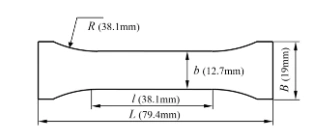 | Unreinforced and reinforced plastics with a stiffness up to 41 Gpa (e.g., also GFRP fabric composites) |
| DIN EN 2850 Method B | B1, Type Ⅲ, Compression strength specimen | 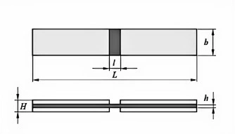 | Nominal specimen length L=80 mm, EN 2850 Method B allows a specimen length between 75 and 80 mm. Specimen width b varies between 12.5 and 15 mm, free specimen length I between 4.75 and 5 mm, depending on the standard. DIN EN 2850 Method B specifies a nominal laminate thickness h of 2 mm. SACMA SRM-1R-94 recommends a laminate thickness of 1.02 mm for UD and 3.05 mm fabric composites. |
B2 Type IV Compression modulus specimen | 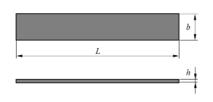 | ||
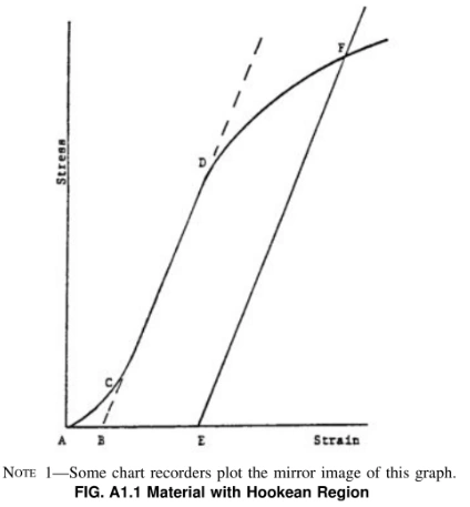
In a typical stress-strain curve (Fig.A1.1) there is a toe region,AC, that does not represent a property of the material. It is an artifact caused by a take up of slack,and alignment or seating of the specimen.In order to obtain correct values of such parameters as modulus,strain.and offset yield point, this artifact must be compensated for to give the corrected zero point on the strain or extension axis.
In the case of a material exhibiting a region of Hookean (linear) behavior (Fig.A1.1), a continuation of the linear(CD) region of the curve is constructed through the zero-stress axis. This intersection(B)is the corrected zero-strain point from which all extensions or strains must be measured,including the yield offset(BE),if applicable.The elastic modulus can be determined by dividing the stress at any point along the line CD (or its extension)by the strain at the same point (measured from Point B, defined as zero-strain).
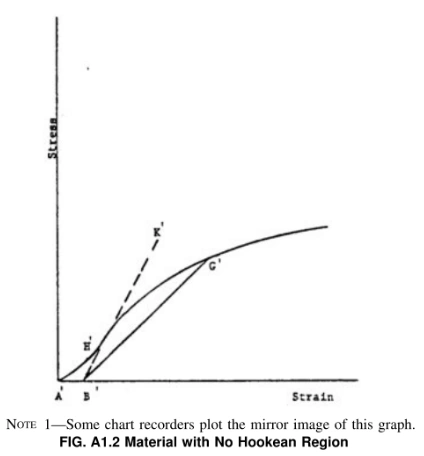
In the case of a material that does not exhibit any linear region (Fig.Al.2) the same kind of toe correction of the zero-strain point can be made by constructing a tangent to the maximum slope at the inflection point(H’).This is extended to intersect the strain axis at Point B. the corrected zero-strain point. Using Point B’ as zero strain, the stress at any point(G’) on the curve can be divided by the strain at that point to obtain a secant modulus (slope of line B’ G’). For those materials with no linear region, any attempt to use the tangent through the inflection point as a basis for determination of an offset yield point may result in unacceptable error..