Fatigue Testing Systems
Electric Fatigue testing systems
Home>>Dynamic Testing Systems>>Electric Fatigue Testing Systems
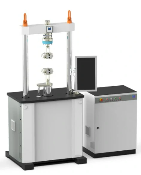
Electric Fatigue Testing Systems
The electric fatigue testing systems can perform fatigue tests on specimens, and the test space is adjustable. It has the characteristics of small footprint, high integration, and high equipment precision.
SINOTEST’s electric fatigue testing systems offers incredible versatility in testing solutions in a number of different industries, including biomedical, orthopaedics, consumer electronics, and research institutions. Our customers’ success has become a major drive of the SINOTEST’s business. We have been with them throughout their journey, proving to be a reliable partner for the last decade. We are passionate about our customers and want to help make testing as exciting and simple as it can be.
With a dynamic load capacity of up to 100kN, an efficient, clean, and low-noise electrodynamic testing system is highly suitable for conducting low load fatigue testing. The system has intuitive system display and visual testing settings, test creation, operation, and data processing functions. Its advanced system design concept ensures the accuracy and reliability of experiments.
Capacity: 10-100KN, 0.1-15Hz
Model: DDPL-10 / DDPL-30 / DDPL-50 / DDPL-100
Application:
- Dynamic Mechanical Analysis (DMA)
- Tension
- Torsion
- Small load test
- Fatigue test
Test Workpiece:
- Polymers: Elastomeric Materials, Elastomers, Plastics, Polymers, Rubber
- Biomaterials and Medical Devices
- Composites: Carbon Fiber, Ceramic Matrix Composites, Composites, Metal Matrix Composites, Polymer Matrix
- Ceramics
- Consumer Products & Packaging
Test Standards:
- ISO 14801, ISO 6475, ASTM F1717, ASTM F2077, ISO 7206
Technical Specification
No. | Technical Name | Technical Indicator |
1 | Max. Static Test Force | ±10kN |
2 | Max. Dynamic Test Force | ±8kN |
3 | Recommended Dynamic Test Force | ≤±8kN |
4 | Test Force Measurement Range | 4-100%FS |
5 | Load Static Measurement Accuracy | ≤±0.5% of indicated value |
6 | Load Dynamic Measurement Accuracy | ≤±2.0% of indicated value |
7 | Actuator Displacement Stroke | ±100mm |
8 | Displacement Measurement Accuracy | ≤±0.5% of indicated value (Calibrated from 10% FS) |
9 | Test Frequency Range | 0.01-15Hz |
10 | Effective Column Span | 615mm |
11 | Vertical Test Space (Room Temp. Fixture Gap) | 50-200 mm |
12 | Overall Dimensions (W×D×H) | 1100×650×2300 mm |
13 | Weight | Approx. 650 kg |
No. | Technical Name | Technical Indicator |
1 | Max. Static Test Force | ±30kN |
2 | Max. Dynamic Test Force | ±24kN |
3 | Recommended Dynamic Test Force | ≤±24kN |
4 | Test Force Measurement Range | 4-100%FS |
5 | Load Static Measurement Accuracy | ≤±0.5% of indicated value |
6 | Load Dynamic Measurement Accuracy | ≤±2.0% of indicated value |
7 | Actuator Displacement Stroke | ±100mm |
8 | Displacement Measurement Accuracy | ≤±0.5% of indicated value (Calibrated from 10% FS) |
9 | Test Frequency Range | 0.01-15Hz |
10 | Effective Column Span | 615mm |
11 | Vertical Test Space (Room Temp. Fixture Gap) | 50-200 mm |
12 | Overall Dimensions (W×D×H) | 1100×650×2300 mm |
13 | Weight | Approx. 800 kg |
No. | Technical Name | Technical Indicator |
1 | Max. Static Test Force | ±50kN |
2 | Max. Dynamic Test Force | ±40kN |
3 | Recommended Dynamic Test Force | ≤±40kN |
4 | Test Force Measurement Range | 4-100%FS |
5 | Load Static Measurement Accuracy | ≤±0.5% of indicated value |
6 | Load Dynamic Measurement Accuracy | ≤±2.0% of indicated value |
7 | Actuator Displacement Stroke | ±100mm |
8 | Displacement Measurement Accuracy | ≤±0.5% of indicated value or 0.1mm, whichever is greater |
9 | Test Frequency Range | 0.01-15Hz |
10 | Effective Column Span | 615mm |
11 | Vertical Test Space (Room Temp. Fixture Gap) | 50-200 mm |
12 | Overall Dimensions (W×D×H) | 1100×650×2300 mm |
13 | Weight | Approx. 950 kg |
No. | Technical Name | Technical Indicator |
1 | Max. Static Test Force | ±100kN |
2 | Max. Dynamic Test Force | ±80kN |
3 | Recommended Dynamic Test Force | ≤±80kN |
4 | Test Force Measurement Range | 4-100%FS |
5 | Load Static Measurement Accuracy | ≤±0.5% of indicated value |
6 | Load Dynamic Measurement Accuracy | ≤±1.0% of indicated value |
7 | Actuator Displacement Stroke | ±100mm |
8 | Displacement Measurement Accuracy | ≤±0.5% of indicated value or 0.1mm, whichever is greater |
9 | Test Frequency Range | 0.01-15Hz |
10 | Effective Column Span | 615mm |
11 | Vertical Test Space (Room Temp. Fixture Gap) | 50-300 mm |
12 | Overall Dimensions (W×D×H) | 1100×645×2300 mm |
13 | Weight | Approx. 1150 kg |
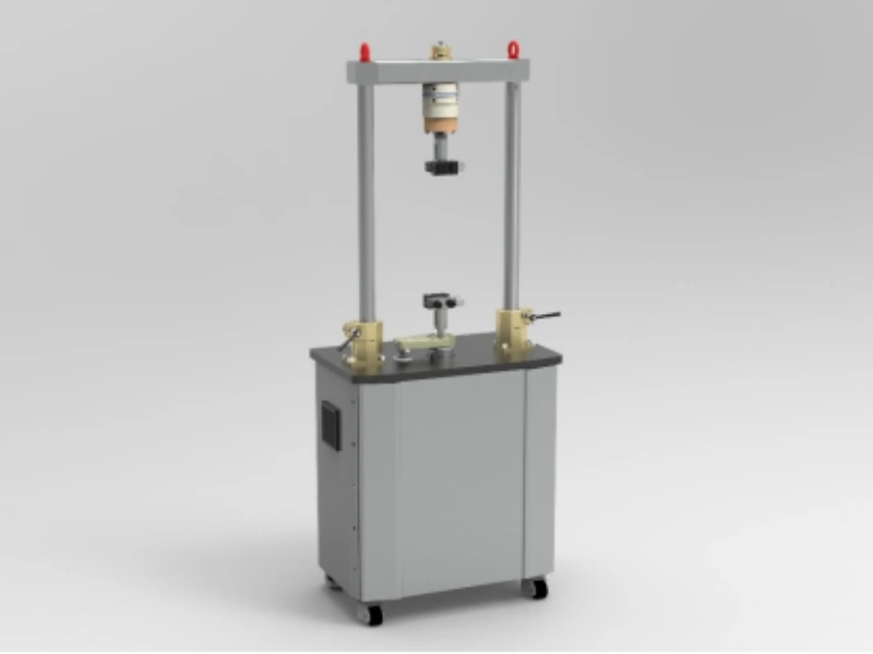
The Electric Fatigue Series Testing Machine includes a range of products such as uniaxial axial loading test models, tension-torsion composite synergistic loading test models, and benchtop models. By matching different environmental devices and tooling fixtures, it can achieve a wide variety of application tests.
Equipped with standard room-temperature mechanical fatigue fixtures, it can perform tests such as tension, compression, and fatigue on standard material specimens (bars/plates) under room-temperature conditions. To meet different specimen requirements, hydraulic fixtures or pneumatic fixtures can be equipped.
Equipped with standard high-temperature fixtures and high-temperature environmental devices, it can perform tests such as tension (threaded bars/pin-hole plates) and compression (threaded bars) fatigue on standard material specimens under high-temperature conditions.
Equipped with standard high/low-temperature fixtures and high/low-temperature environmental devices, it can perform tests such as tension (threaded bars/pin-hole plates) and compression (threaded bars) fatigue on standard material specimens under high/low-temperature conditions.
Note: Standard material specimens should comply with the relevant requirements of Chapter 5 of GB/T 3075-2008 “Metallic Materials – Fatigue Testing – Axial Force-Controlled Method,” Chapter 6 of GB/T 15248-2008 “Metallic Materials – Axial Constant Amplitude Low-Cycle Fatigue Testing Method,” and Chapter 5 of GB/T 3354-1999 “Test Method for Tensile Properties of Oriented Fiber-Reinforced Plastics.”
The Electric Fatigue Series Testing Machine is equipped with a comprehensive safety alarm system, enabling unattended operation during tests. The software can set upper and lower limit protections for load and displacement respectively. If the limits are exceeded, the host machine will stop working to ensure test safety. The hardware can monitor motor phase loss, motor overcurrent, emergency stops, etc. If any of these protections are triggered, the system will automatically alarm or shut down.
▪FOB
▪CIF
▪Package: Wooden case
Download Catalog