The ASTM D790 standard describes a test method used to determine the flexural properties of unreinforced and reinforced plastics, including high modulus composites and electrical insulating materials. Typical test results according to ASTM D790 include the flexural modulus, stresses and strains at the yield point, the flexural strength and the flexural strain at break. The tests are used for rigid and semi-rigid plastics, however only up to a 5% strain limit.
Objective & characteristic values of ASTM D790
The 3-point flexure test to ASTM D790 is a traditional standardized characterization method for rigid and semi-rigid plastics. The flexural properties determined with these tests are of great importance to designers, engineers and material manufacturers to ensure that the plastic material used meets the requirements for its intended application.
Flexural modulus: The flexural modulus is a measure of the stiffness of the material and indicates how well it can resist flexural loads. The ASTM D790 standard provides three calculation methods for the flexural modulus, each of which leads to different results:
Tangent Modulus (Modulus of Elasticity): The ratio, within the elastic limit, of stress corresponding to strain
Secant Modulus: Ratio of stress to corresponding strain at any selected point on the stress-strain curve
Chord Modulus: Slope between two specified points on the stress-strain curve
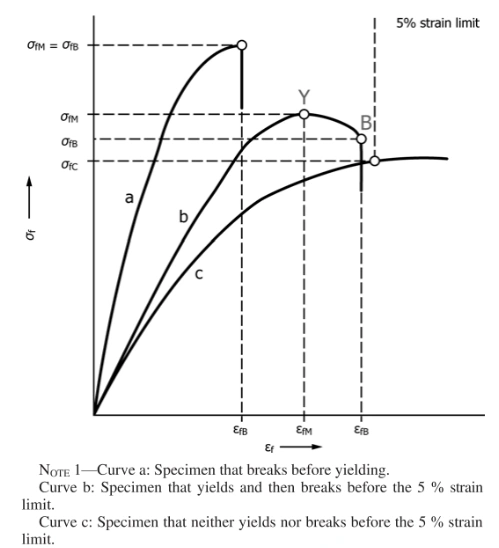
Flexural strength: Flexural strength provides information about the maximum load that the material can withstand in flexure before it breaks.
Flexural stress at a specified flexural strain
Flexural stresses and flexural strains at the yield point and at specimen break.
This technique is needed to ensure that the correct span; not an estimated span,is used in the calculation of results.
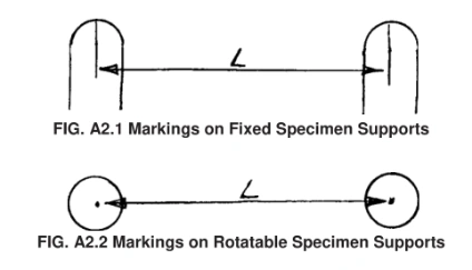
Scribe a permanent line or mark at the exact center of the support where the specimen makes complete contact. The type of mark depends on whether the supports are fixed or rotatable (see Figs.A2.1 and A2.2).
Using a vernier caliper with pointed tips that is readable to at least 0.1mm(0.004 in.), measure the distance between the supports,and use this measurement of span in the calculations.
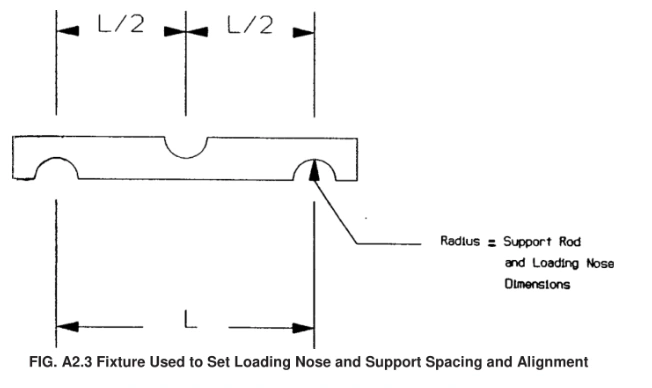
Setting the Span and Alignment of Loading Nose(s)— To ensure a consistent day-to-day setup of the span and ensure the alignment and proper positioning of the loading nose, simple jigs should be manufactured for each of the standard setups used.An example of a jig found to be useful is shown in Fig.A2.3.