
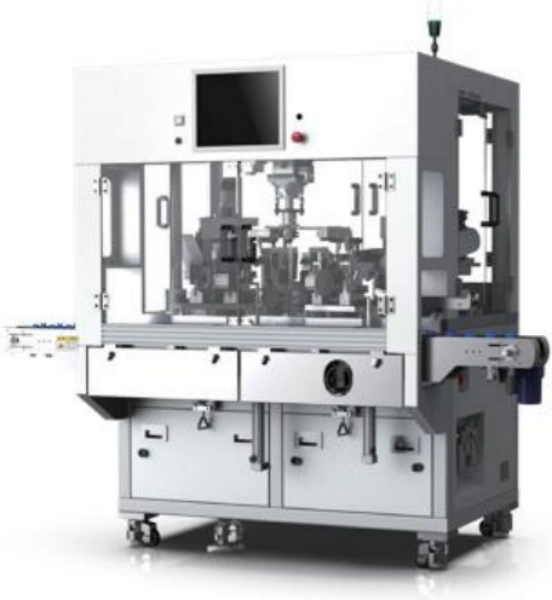
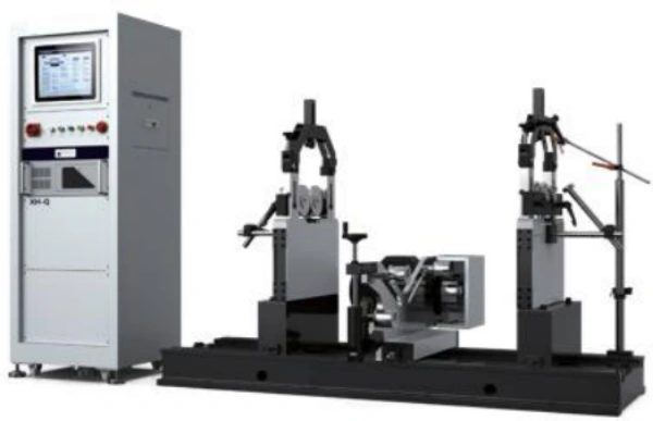
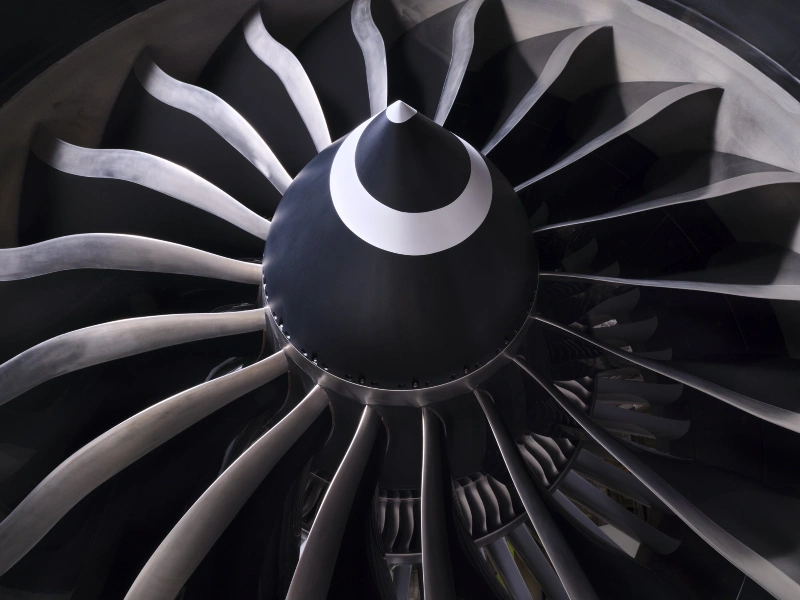
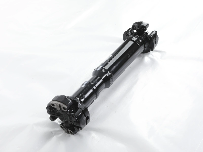
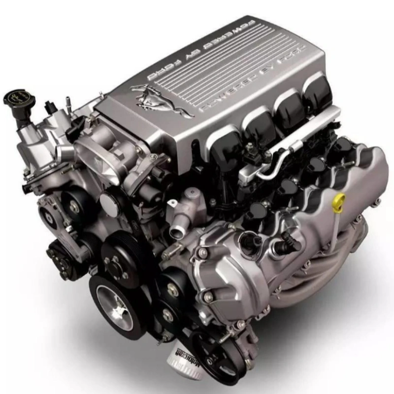
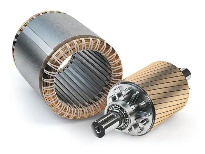
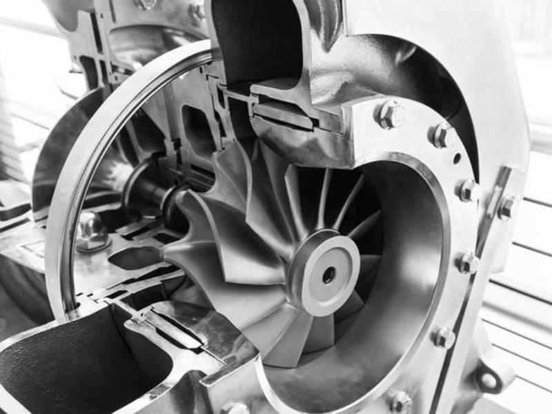
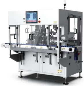
Mainly suitable for automatic balance correction of motor rotors in vacuum cleaners, garden tools, power tools, cars, and other applications. (Can be linked to a fully automatic rotor production line)
Project Details | Parameter Range |
Equipment appearance dimensions | 1640*1400*1800mm |
Cycle time | 9-15s |
Workpiece height range | 20-60mm |
Workpiece diameter range | Φ20-60mm |
Balance speed | 1200-3400rpm |
Balance correction method | R/V cutter |
Reduction rate of unbalance | URR≥95% (Depending on theinitial rotorvalue) |
Minimum attainable residual imbalance | ≤0.3g.mm/kg |
Drive mode | O-ring drive |
Equipment power supply | Three phase five wire 380V AC |
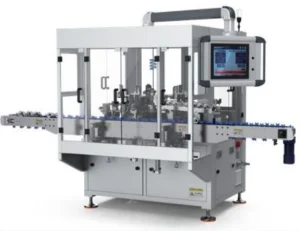
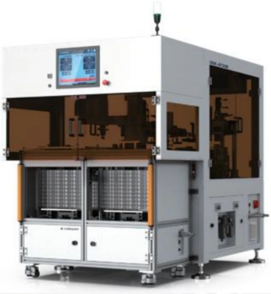
Mainly suitable for automatic balance correction of brushless motor rotors in washing machines, power tools, cars, and other applications. (Can be linked to a fully automatic rotor production line)
Project Details | Parameter Range |
Equipment appearance dimensions | 1640*1400*1800mm |
Cycle time | 8-14s |
Workpiece height range | 20-60mm |
Workpiece diameter range | Φ25-60mm |
Balance speed | 1500-3200rpm |
Balance correction method | Straight milling cutter |
Reduction rate of unbalance | URR≥95% (Depending on theinitial rotorvalue) |
Minimum attainable residual imbalance | ≤0.3g.mm/kg |
Drive mode | O-ring drive |
Equipment power supply | Three phase five wire 380V AC |
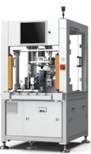
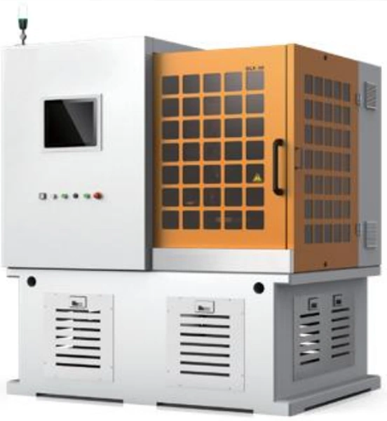
Mainly suitable for automatic balance correction of motor rotors, such as those used in brushless power tools. (It can be integrated with fully automated rotor production lines)
Project Details | Parameter Range |
Equipment appearance dimensions | 1600*1500*1670mm |
Cycle time | 12-18s |
Workpiece diameter range | Φ16-33mm |
Balance speed | 1500-3400rpm |
Balance correction method | Milling / Drilling |
Reduction rate of unbalance | URR≥95% (Depending on theinitial rotorvalue) |
Minimum attainable residual imbalance | ≤0.3g.mm/kg |
Drive mode | O-ring drive |
Equipment power supply | AC 220V |
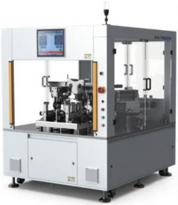
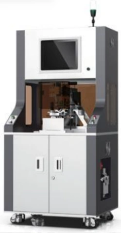
Mainly suitable for automatic balance correction of generator rotors.
Project Details | Parameter Range |
Equipment appearance dimensions | 1400*1600*1800mm |
Cycle time | 40-45s |
Workpiece height range | 20-60mm (standard) |
Workpiece diameter range | Φ 80-120mm (standard) |
Balance speed | 1200-2600rpm |
Balance correction method | Drill hole |
Reduction rate of unbalance | URR≥90% |
Minimum attainable residual imbalance | ≤0.3g.mm/kg |
Drive mode | O-ring drive |
Equipment power supply | Three phase five wire 380V AC |
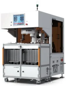
Mainly suitable for dynamic balance testing and fully automatic weight correction of axial fans, centrifugal fans, rotors and other products with shaft discs.
Project Details | Parameter Range |
Equipment appearance dimensions and Tray disk dimensions | 1200*2000*1800mm / 455*490mm |
Equipment functions | Automatic loading and unloading/automatic testing/automatic dispensing |
Equipment usage scope | Fan blade diameter 20-80mm (suitable for axial rotors) |
Estimated production capacity | UPH 100-130pcs (depending on the product) |
Balance speed | 1400-5600rpm |
Balance correction method | Glue dispensing with quality |
Reduction rate of unbalance | URR≥90% |
Minimum balance correction accuracy | Precision ≤ 0.2mg/Conventional ≤ 1.5mg (depending on the product) |
Balance surface number | Single-side/Double-side/Triple-side |
Equipment power supply, gas supply, and power | Three phase five wire 380V AC / 0.4-0.6Mpa / 10KW |
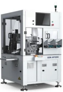
Mainly suitable for dynamic balance testing and fully automatic weight reduction correction of axial fans, centrifugal fans and other products with shaft discs.
Project Details | Parameter Range |
Equipment appearance dimensions | 1100*1350*1860mm |
Equipment functions | Automatic testing/automatic milling |
Equipment usage scope | Fan blade diameter 30-140mm (suitable for axial rotors) |
Estimated production capacity | UPH 100-120pcs (depending on the product) |
Balance speed | 1400-5600rpm |
Balance correction method and milling cutter diameter | Drill/milling cutter cutting / Ф2-Ф8mm |
Reduction rate of unbalance | URR≥90% |
Minimum balance correction accuracy | Precision ≤ 0.2mg/Conventional ≤ 1.5mg (depending on the product) |
Balance surface number | Single-side/Double-side/Triple-side |
Equipment power supply, gas supply, and power | Three phase five wire 380V AC / 0.4-0.6Mpa / 8KW |
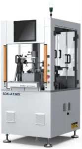
Mainly suitable for dynamic balance testing and fully automatic weight reduction correction of various cooling fans such as axial fans and centrifugal fans.
Project Details | Parameter Range |
Equipment appearance dimensions | 850*1080*1830mm |
Equipment functions | Automatic loading and unloading/automatic testing/automatic milling |
Equipment usage scope | Fan blade diameter 40-140mm (suitable for axial rotors) |
Estimated production capacity | UPH 100-130pcs (depending on the product) |
Balance speed | 1400-5600rpm |
Balance correction method and milling cutter diameter | T-shaped milling cutter / Ф6, Ф8, Ф10mm (customizable cutting tools) |
Reduction rate of unbalance | URR≥90% |
Minimum balance correction accuracy | Precision ≤ 0.2mg/Conventional ≤ 1.5mg (depending on the product) |
Balance surface number | Single-side/Double-side/Triple-side |
Equipment power supply, gas supply, and power | Three phase five wire 380V AC / 0.4-0.6Mpa / 8KW |
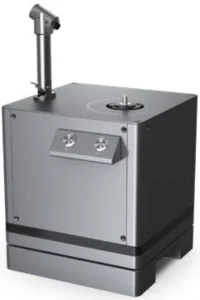
Mainly suitable for dynamic balance test of various airfoils with and without shafts.
-High precision and efficiency: Using high-precision spindle to clamp the fan for rotation, the highest dynamic balance accuracy can reach below ISO1940 G1.0.The spindle or sleeve can be quickly replaced.
-High reproducibility: High reproducibility GRR<10%.
-Eccentricity compensation: Equipped with an eccentricity compensation function, it solves the balance measurement problem caused by poor verticality and concentricity of the fan blades, greatly improving the balance accuracy.
-Power system: Equipped with a servo motor power system, it can drive the fan blades to rotate and automatically position.
Project Details | Parameter Range |
Equipment appearance dimensions | 230*250*405mm |
Range of rotor diameter | Ф20-Ф90mm |
Range of rotor quality | 2-90g |
Fan blade axis diameter | Ф0.6-Ф3.175mm |
Balance speed | 1000-8000rpm |
Fan blade drive mode | Servo motor+O-ring |
Reduction rate of unbalance | URR≥95% |
Balance display accuracy | 0.01mg |
Balance surface number | Single-side/Double-side/Triple-side |
Equipment power supply and air pressure requirements | 220V AC 50Hz / 0.3MPa |
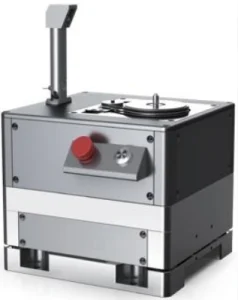
Mainly suitable for dynamic balance test of various airfoils with and without shafts.
-high precision and efficiency: Using high-precision spindle to clamp the fan for rotation, the
-highest dynamic balance accuracy can reach below ISO1940 G1.0.The spindle or sleeve can be quickly replaced.
-High reproducibility: High reproducibility GRR<10%.
Eccentricity compensation: Equipped with an eccentricity compensation function, it solves the balance measurement problem caused by poor verticality and concentricity of the fan blades, greatly improving the balance accuracy.
Power system: Equipped with a servo motor power system, it can drive the fan blades to rotate and automatically position.
Project Details | Parameter Range |
Equipment appearance dimensions | 240*245*325mm |
Range of rotor diameter | Ф20-Ф90mm |
Range of rotor quality | 2-90g |
Fan blade axis diameter | Ф0.6-Ф3.175mm |
Balance speed | 1000-8000rpm |
Fan blade drive mode | Self driven spindle |
Reduction rate of unbalance | URR≥95% |
Balance display accuracy | 0.01mg |
Balance surface number | Single-side/Double-side/Triple-side |
Equipment power supply and air pressure requirements | 220V AC 50Hz / 0.3MPa |
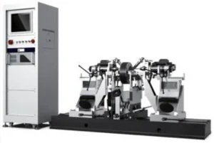
Mainly suitable for dynamic balance testing of general motor
rotors and drum products.
High precision: Qualified range determination, high measurement accuracy.
Easy to operate: Strong universality and easy adjustment; No need for repeated calibration; Modular structure, easy and flexible upgrade.
Project Details | Parameter Range |
Maximum rotor weight | 300kg |
Maximum rotor diameter | 1200mm |
Cross-rod support range | 10-70mm |
Expandable cross-rod support range | 70-140mm |
Balance speed | 220-3800rpm |
Drive power | 3KW |
Reduction rate of unbalance | URR≥95% |
Minimum attainable residual imbalance | ≤0.5g.mm/kg |
Drive mode | belt transmission |
Equipment power supply | Three phase five wire 380V AC |
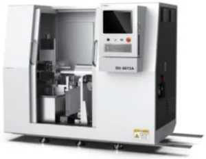
Mainly suitable for dynamic balance detection of rotors in new energy motors.
High precision and efficiency: High precision and efficiency: automat- ic/semi-automatic selectable; Suitable for large stack thickness/long axis products, capable of axial drilling; Suitable for multiple varieties, large-scale production, and easy changeover.
Project Details | Parameter Range |
Equipment appearance dimensions | 2700*1300*1900mm |
Cycle time | 90-120s |
Allowable range of supporting shaft diameter for the support frame | Φ20-80mm |
Allow clamping of rotor diameter range / drilled diameter | Φ130-300mm / Φ16mm |
Allow to support the total length of the rotor / Maximum rotor mass | ≤600mm / ≤20kg |
Range of support distance adjustment | 200-540mm |
Balance speed | 1000-6000rpm |
Balance display accuracy | 0.1mg |
Reduction rate of unbalance | URR≥90% |
Minimum attainable residual imbalance | ≤0.1g.mm/kg |
Drive mode | belt transmission |
Equipment power supply | 三相五线380V AC Three phase five wire 380V AC |
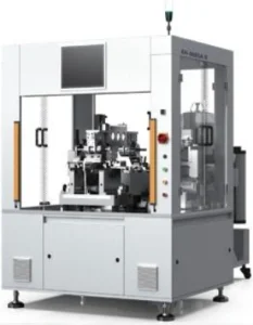
Mainly suitable for automatic balance correction of motor rotors in water pumps, transmission rotors, washing machines, power tools, new energy vehicles, and other applications.
Project Details | Parameter Range |
Equipment appearance dimensions | 1480*1200*1800mm |
Cycle time | 40-45s |
Workpiece height range | 50-200mm |
Workpiece diameter range | Φ40-120mm |
Workpiece quality range | 1-5kg |
Balance speed | 1200-3000rpm |
Balance correction method | Drill hole |
Balance display accuracy | 0.1mg |
Reduction rate of unbalance | URR≥95% |
Minimum attainable residual imbalance | ≤0.1g.mm/kg |
Drive mode | belt transmission |
Equipment power supply | Three phase five wire 380V AC |
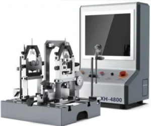
Mainly suitable for dynamic balance testing of plastic, aluminum alloy fan blades and rotors.
High precision and efficiency: The data acquisition system has strong anti-interference ability, high stability, and accurate measurement; Industrial computer measurement system, with strong universality and easy adjustment.
Easy to operate: Measurement is carried out through servo motor belt transmission, and the operation is simple and easy to understand. The measurement
sensor uses an accelerometer as the signal source, which is small in size, has good linearity, is maintenance free, and has a long lifespan.
Project Details | Parameter Range |
Equipment appearance dimensions | 500*450*760mm |
Distance between two supports | 60-320mm |
Roller support journal range | Φ6-25mm |
Workpiece diameter range | Φ20-120mm |
Workpiece quality range | 0.2-3kg |
Reduction rate of unbalance | URR≥95% |
Minimum attainable residual imbalance | ≤0.3g.mm/kg |
Drive mode | Flat belt |
Equipment power supply | 220V/50Hz |
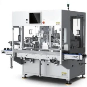
Mainly suitable for vertical double-sided automatic balancing of various fan external rotors.
Project Details | Parameter Range |
Equipment appearance dimensions | 2450*1400*1800mm |
Cycle time | ≤45s |
Workpiece height range | 30-50mm |
Workpiece diameter range | Φ80-130mm |
Workpiece quality range | 0.2-1kg |
Balance speed | 1200-3200rpm |
Balance correction method | Ring milling |
Balance display accuracy | 1mg |
Reduction rate of unbalance | URR≥90% |
Minimum attainable residual imbalance | ≤1g.mm/kg |
Drive mode | belt transmission |
Equipment power supply | Three phase five wire 380V AC |
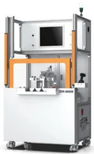
Mainly suitable for balance testing of motor rotors such as water pumps, transmission rotors, washing machines, power tools, and new energy vehicles.
Project Details | Parameter Range |
Equipment appearance dimensions | 1170*850*1800mm |
Cycle time | 40-45s |
Workpiece height range | 50-200mm |
Workpiece diameter range | Φ40-120mm |
Workpiece quality range | 1-5kg |
Balance speed | 1200-3000rpm |
Balance correction method | Drill hole |
Balance display accuracy | 0.1mg |
Reduction rate of unbalance | URR≥95% |
Minimum attainable residual imbalance | ≤0.1g.mm/kg |
Drive mode | belt transmission |
Equipment power supply | Three phase five wire 380V AC |
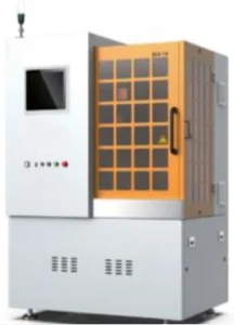
Mainly suitable for automatic balance correction of disc rotors such as flywheels, pulleys, brake drums, gears, clutches, flanges, planetary carriers, differential housings, brake discs, water pump impellers, flanges, and pulleys.
Project Details | DLX3 | DLX5 | DLX10 | DLX16 | DLX30 | DLX42 |
Equipment appearance dimensions | 800*1400*1700 | 900*1450*1800 | 1400*1050*1850mm | 1700*1250*1970mm | ||
Cycle time | ≤ 50s (arc cutting) | 60-80s one-time milling (secondary milling not exceeding 2 minutes) | ||||
Workpiece height range | ≤80mm | ≤120mm | ≤160mm | ≤200mm | ≤300mm | |
Workpiece outer diameter range and milling diameter | Φ35-120mm | Φ60-250mm | Φ100-350mm | Φ180-450mm | Φ250-550mm | |
Workpiece quality range | 3kg | 5kg | 10kg | 16kg | 35kg | 42kg |
Balance speed | ≤2400rpm | ≤1800rpm | ≤1200rpm | |||
Balance correction method | Arc milling/axial drilling/radial drilling | |||||
Maximum milling depth | ≤10mm | |||||
Reduction rate of unbalance | URR≥90% | |||||
Minimum attainable residual imbalance | ≤1g.mm/kg | |||||
Balance motor power | 2KW | |||||
Laser engraving machine power | 50W | |||||
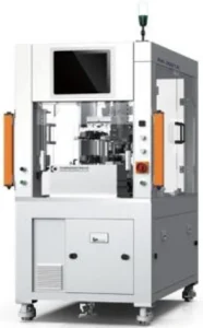
Mainly suitable for automatic balance correction of single-sided disc products.
Project Details | Parameter Range |
Equipment appearance dimensions | 830*1300*1700mm |
Cycle time | 10-15 seconds (based on 3 holes) |
Workpiece height range | ≤120mm |
Workpiece diameter range | Φ20-150mm |
Workpiece quality range | 0.1-1kg |
Balance speed | 1000-4800rpm |
Balance correction method | Milling cutter/drill bit cutting |
Balance display accuracy | 0.1mg |
Reduction rate of unbalance | URR≥95% |
Minimum attainable residual imbalance | ≤0.2g.mm/kg |
Drive mode | Servo drive |
Equipment power supply | 220V/50HZ |
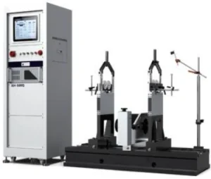
Mainly suitable for dynamic balance testing of general motor rotors and drum products.
High precision and efficiency: High measurement accuracy; Strong universality, no need for repeated calibration; Upgrades are convenient and flexible.
Project Details | Parameter Range |
Equipment appearance dimensions | 1500*870*1250mm |
Machine bed length / Maximum distance between two supports | 1500mm / 1350mm |
Cross-rod support range / Expandable cross-rod support range | 10-140mm / 70-140mm |
Workpiece diameter range | 1500mm |
Workpiece quality range | 500kg |
Balance speed | 220-3800rpm |
The minimum distance between the driving device and the two supporting swing frames | 150mm |
Drive power | 3KW |
Reduction rate of unbalance | URR≥95% |
Minimum attainable residual imbalance | ≤0.5g.mm/kg |
Drive diameter at the belt drive | 20-450mm |
When the diameter of the belt drive is | 100mm |
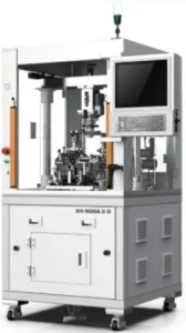
Mainly suitable for high-speed dynamic balancing of small rotors in micro motors and brushless motor rotors.
Project Details | Parameter Range |
Equipment appearance dimensions | 950*950*1830mm |
Cycle time | 12-14s (based on 2 holes) |
Workpiece height range | 8-60mm |
Workpiece diameter range | Φ14-50mm |
Workpiece quality range | 0.01-0.3kg |
Balance speed | 2000-10000rpm |
Balance correction method | Drill/milling cutter |
Balance display accuracy | 0.1mg |
Reduction rate of unbalance | URR≥95% |
Minimum attainable residual imbalance | ≤0.3g.mm/kg |
Drive mode | O-ring drive |
Equipment power supply | 220V/50Hz |
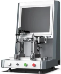
Mainly suitable for dynamic balance testing of precision rotors such as brushless vacuum cleaner motor rotors, brushless power tool rotors, brush- less blower components, robot joint motor rotors, gyroscope rotors, etc.
High precision and efficiency: high precision, good repeatability in linearity; Support data storage and uploading to MES system; Barcode input with strong traceability; The radar chart on the dynamic balance screen displays the unbalance value.
Project Details | Parameter Range |
Equipment appearance dimensions | 470*520*680mm |
Workpiece diameter range | Φ3-36mm |
Workpiece quality range | 0.001-0.1kg |
Supporting rotor span | 20-120mm |
Balance speed | 1200-10000rpm |
Unbalanced quantity detection / Unbalanced quantity angle detection | Accelerometer / Laser sensor/magnetic pole sensor |
Balance surface number | Single-side/Double-side |
Balance display accuracy | 0.1mg |
Reduction rate of unbalance | URR≥95% |
Minimum attainable residual imbalance | ≤0.1g.mm/kg |
Drive mode | O-ring drive |
Equipment power supply | 220V/50Hz |
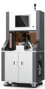
Mainly suitable for overall balancing of high-speed brushless
vacuum cleaner motors and DC brushed fans. (Automatic loading and unloading positions can be reserved for easy automation transformation)
Project Details | Parameter Range |
Equipment appearance dimensions | 800*660*1690mm |
Cycle time | ≤25s |
Workpiece diameter range | Φ 30-80mm (size of motor fixing point) |
Balance speed | 3000-45000rpm |
Balance correction method | Scissor cutting |
Balance display accuracy | 0.1mg |
Reduction rate of unbalance | URR≥95% |
Minimum attainable residual imbalance | ≤0.5g.mm/kg |
Drive mode | Self driven |
Equipment power supply | 220V/50Hz |
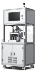
Mainly suitable for laser automatic correction and balance of precision rotors such as brushless rotors, vacuum cleaner motor rotors, brushless power tools, electric toothbrush rotors, hollow cup motor rotors, ventilator rotors, robot joint motor rotors, gyroscope rotors, etc.
Project Details | Parameter Range |
Equipment appearance dimensions | 800*680*1800mm |
Cycle time | 60s |
Workpiece diameter range | Φ3-15mm |
Workpiece quality range | 0.002-0.03kg |
Supporting rotor span | 20-110mm |
Balance speed | 2000-10000rpm |
Balance correction method | Laser correction |
Balance surface number | Double-sided |
Balance display accuracy | 0.1mg |
Reduction rate of unbalance | URR≥95% |
Minimum attainable residual imbalance | ≤0.5g.mm/kg |
Drive mode | Servo+belt drive |
Equipment power supply | 220V/50Hz |
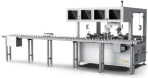
Mainly suitable for laser automatic correction balance of high-speed rotor/rotor components such as high-speed hair dryer rotor components, high-speed vacuum cleaner rotor components, dental drill rotor, gyroscope rotor, ventilator motor rotor, etc.
Project Details | Parameter Range |
Equipment appearance dimensions | 6600*1950*1850mm |
Cycle time | 60s (original unbalance ≤15mg) |
Workpiece diameter range | Φ6-32mm |
Workpiece quality range | 0.01-0.3kg |
Supporting rotor span | 20-90mm |
Balance speed | 2000-10000rpm |
Balance correction method | Dual laser correction |
Unbalanced quantity detection / Unbalanced quantity angle detection | Accelerometer / Laser sensor |
Balance surface number | Single sided/double-sided |
Balance display accuracy | 0.1mg |
Reduction rate of unbalance | URR≥90% |
Minimum attainable residual imbalance | fan blade end ≤ 0.5mg, magnetic ring end ≤ 1mg |
Drive mode | O-ring |
Equipment power supply | 220V/50Hz |
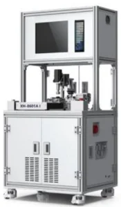
Mainly suitable for the dynamic balancing of micro precision products such as
high-speed hair dryer motors, high-speed vacuum cleaner motors, sweeping machine motors, suction pumps, dental drills, ventilator motors, and cooling fans.
Project Details | Parameter Range |
Equipment appearance dimensions | 800*650*1700mm |
Cycle time | 30s (original unbalance ≤ 8mg) |
Impeller diameter range | Φ10-50mm |
Determination of duplicate location | CCD |
Dust removal method | Electric pulse dust removal |
Balance speed | 6000-150000rpm |
Balance correction method | Laser correction |
Balance surface number | Single-sided |
Balance display accuracy | 0.1mg |
Reduction rate of unbalance | URR≥90% |
Minimum attainable residual imbalance | ≤0.5g.mm/kg |
Drive mode | Self driving (customer provided power supply) |
Equipment power supply and gas source | 220V/50Hz / 0.4-0.6Mpa |
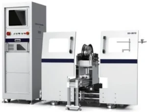
Mainly suitable for dynamic balance testing of general motor rotors and drum products.
High precision and efficiency: Accurate measurement and stable data; Strong universality and easy adjustment; Upgrades are convenient and flexible.
Project Details | Parameter Range |
Equipment appearance dimensions | 1500*1200*1250mm |
Workpiece diameter range | Φ 1000mm (maximum at the loop is Φ 300mm) |
Workpiece quality range | 5-50kg |
Supporting rotor span | 200-1000mm |
Supporting spindle maximum diameter | Φ180mm |
Spindle balance speed / Rotor balance speed | 800-25000rpm (maximum 10w rpm for self rotating type) / 800-8000rpm |
Unbalanced quantity detection / Unbalanced quantity angle detection | Accelerometer×2 / High frequency laser sensor |
Balance surface number | Single sided/double-sided |
Tightening method | Cylinder tightening |
Spectrum analysis function | Dual channel FFT |
Minimum attainable residual imbalance | ≤0.5g.mm/kg (low speed) / 0.05g.mm/kg (high speed) |
Drive mode / Motor driver power | Belt Drive/Motor Self Drive / 3.7kw |
Equipment power supply | Three phase five wire 380V AC |
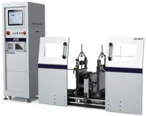
Mainly suitable for automatic balance correction of machine tools/high-speed concealed spindles, motor rotors/motors, rollers, fans, and coreless grinding wheels.
Project Details | Parameter Range |
Equipment appearance dimensions | 1500*690*1130mm |
Workpiece diameter range | Φ 1000mm (maximum at the loop is Φ 300mm) |
Workpiece quality range | 5-150kg |
Supporting rotor span | 200-1260mm |
Supporting spindle maximum diameter | Φ180mm |
Spindle balance speed / Rotor balance speed | 800-25000rpm (maximum 10w rpm for self rotating type) / 800-8000rpm |
Unbalanced quantity detection / Unbalanced quantity angle detection | Accelerometer×2 / High frequency laser sensor |
Balance surface number | Single sided/double-sided |
Tightening method | Cylinder tightening |
Spectrum analysis function | Dual channel FFT |
Minimum attainable residual imbalance | ≤0.5g.mm/kg (low speed) / 0.05g.mm/kg (high speed) |
Drive mode / Motor driver power | Belt Drive/Motor Self Drive / 3.7kw |
Equipment power supply | Three phase five wire 380V AC |
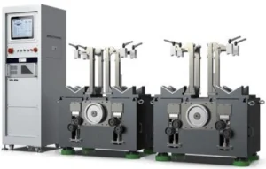
Mainly suitable for running and monitoring the speed and temperature changes of the spindle during the production and maintenance process of machining centers.
Project Details | XH-PH02 | XH-PH04 | XH-PH08 |
Number of running in spindles | 2 | 4 | 8 |
Number of reserved channels | 8 | 4 | 0 |
Motor driver power | 7.5kw | ||
Maximum motor speed | 6000rmp | ||
Range of support distance for running in platform | 50-650mm | ||
Range of supported spindle diameter | Φ50-260mm | ||
Temperature detection sensor model | Thermocouple (temperature resolution 0.1 ℃) | ||
Temperature variation range that can be monitored | 0-120℃ | ||
Maximum spindle drive speed | 24000 (spindle drive diameter 38mm) | ||
Printing format of monitoring results | PDF or paper (editable) | ||
Overall dimensions of appearance | 1120*750*720mm | ||
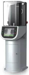
Mainly suitable for single plane and double plane (optional) dynamic balance correction of cutting tools, tool holders, and grinding wheels.
High precision and efficiency: The repeated measurement accuracy is extremely high, with good linearity; Simply connect the power supply and compressed air to the balancing machine to perform dynamic balancing; Enter the tool parameters to complete the calibration operation, which can store different standards without the need for repeated calibration.
Project Details | Parameter Range |
Equipment appearance dimensions | 460*650*1630mm |
Maximum handle diameter | Φ380mm |
Maximum handle weight | 30kg |
Maximum handle length | 400mm |
Spindle balance speed | 300-1100rpm |
Highest measurement accuracy | ≤0.5g.mm/kg |
Reduction rate of unbalance | URR≥95% |
power usage | 0.4kw |
Compressed air | 6bar |
Equipment power supply | 230V/50-60HZ |
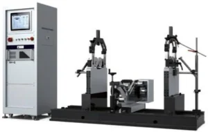
Mainly suitable for dynamic balance testing of general motor rotors and drum products.
Project Details | 300Q | 500Q | 1000Q | 2000Q | 3000Q | 5000Q | 7500Q |
Maximum rotor weight(kg) | 300 | 500 | 1000 | 2000 | 3000 | 5000 | 7500 |
Maximum rotor diameter(mm) | 1200 | 1500 | 1600 | 1600 | 1600 | 2100 | 2100 |
Cross-rod support range(mm) | 10-70 | 10-140 | 15-120 | 15-120 | 25-180 | 25-180 | 40-220 |
Expandable cross-rod support range(mm) | 70-140 | 70-140 | 100-220 | 120-240 | 180-280 | 180-380 | 220-380 |
Minimum attainable residual imbalance(g.mm/kg) | 0.5 | 0.5 | 0.5 | 0.5 | 0.5 | 0.5 | 0.5 |
Reduction rate of unbalance(%) | 95 | 95 | 95 | 95 | 95 | 95 | 95 |
Machine bed length(mm) | 1500 | 1500 | 2000 | 2000 | 3000 | 3000 | 4000 |
Maximum distance between two supports(mm) | 1350 | 1350 | 1740 | 1740 | 2650 | 2550 | 3550 |
The minimum distance between the driving device and the two supporting swing frames(mm) | 150 | 150 | 260 | 260 | 350 | 450 | 450 |
Drive power(kw) | 3 | 3 | 4.5 | 5.5 | 5.5 | 7.5 | 7.5 |
Drive diameter at the belt drive(mm) | 20-350 | 20-450 | 30-600 | 30-600 | 30-800 | 30-1000 | 50-1000 |
Balance speed approximately(r/min) | 220-3800 | 220-3800 | 220-3500 | 220-2500 | 220-2500 | 220-2500 | 220-2500 |
When the diameter of the belt drive is(mm) | 100 | 100 | 100 | 100 | 150 | 150 | 200 |
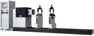
Mainly suitable for dynamic balance testing of large and medium-sized motor rotors, fans, rollers, agricultural machinery and other products.
Project Details | 160W | 300W | 500W | 1000W | 2000W | 3000W | 5000W | 7500W |
Maximum rotor weight(kg) | 160 | 300 | 500 | 1000 | 2000 | 3000 | 5000 | 7500 |
Maximum rotor diameter(mm) | 1000 | 1200 | 1500 | 1600 | 1600 | 1600 | 2100 | 2100 |
Scalable maximum rotor diameter(mm) | 1500 | 1600 | 1600 | 2100 | 2100 | 2400 | 2400 | 2800 |
Cross-rod support range(mm) | 15-70 | 15-70 | 20-140 | 25-140 | 25-180 | 40-180 | 40-180 | 40-180 |
Expandable cross-rod support range(mm) | 70-140 | 70-140 | 120-180 | 120-220 | 180-280 | 180-280 | 180-380 | 180-380 |
Minimum attainable residual imbalance(g.mm/kg) | 0.5 | 0.5 | 0.5 | 1 | 1 | 1 | 1 | 1 |
Reduction rate of unbalance(%) | 95 | 95 | 95 | 95 | 95 | 95 | 95 | 95 |
Machine bed length(mm) | 3000 | 3000 | 3000 | 3000 | 3000 | 4000 | 4000 | 5000 |
The maximum distance from the flange end face of the universal joint to the right support swing frame(mm) | 1750 | 1750 | 1750 | 1550 | 1550 | 2350 | 2350 | 3300 |
Minimum distance from the cente r of the supporting swing frame(mm) | 90 | 90 | 90 | 90 | 110 | 110 | 130 | 240 |
Drive power(kw) | 3 | 3 | 4.5 | 5.5 | 5.5 | 7.5 | 15 | 22 |
Balance speed approximately(r/min) | 230-2800 | 230-2800 | 230-2580 | 230-2380 | 230-2380 | 230-2380 | 230-2380 | 230-2380 |
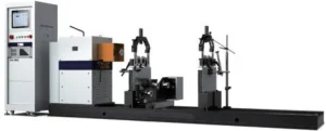
Mainly suitable for dynamic balance testing of fans and drum products.
Project Details | 160WQ | 300WQ | 500WQ | 1000WQ | 2000WQ | 3000WQ | 5000WQ | 7500WQ |
Maximum rotor weight(kg) | 160 | 300 | 500 | 1000 | 2000 | 3000 | 5000 | 7500 |
Maximum rotor diameter(mm) | 1200 | 1200 | 1500 | 1600 | 1600 | 1600 | 2100 | 2100 |
Cross-rod support range/Expandable cross-rod support range(mm) | 10-70 70-140 | 10-70 70-140 | 10-140 70-140 | 15-120 100-220 | 15-120 120-240 | 25-180 180-280 | 25-180 180-380 | 40-220 220-380 |
Reduction rate of unbalance(%) | 95 | 95 | 95 | 95 | 95 | 95 | 95 | 95 |
Machine bed length/Minimum distance from the center of the supporting swing frame(mm) | 3000/90 | 3000/90 | 3000/90 | 3000/90 | 3000/110 | 4000/110 | 4000/130 | 5000/240 |
The maximum distance from the flange end face of the universal joint to the right support swing frame(mm) | 1750 | 1750 | 1750 | 1550 | 1550 | 2350 | 2350 | 3300 |
Drive power(kw) | 1.5 | 3 | 4.5 | 5.5 | 5.5 | 7.5 | 15 | 22 |
Minimum attainable residual imbalance(g.mm/kg) | 0.5 | 0.5 | 0.5 | 1 | 1 | 1 | 1 | 1 |
Maximum/Minimum distance from the center of the supporting swing frame(mm) | 1050/50 | 1350/150 | 1350/150 | 1740/260 | 1740/260 | 2650/350 | 2350/450 | 3350/450 |
Drive power(kw) | 1.5 | 3 | 3 | 4.5 | 5.5 | 5.5 | 7.5 | 7.5 |
Minimum attainable residual imbalance(g.mm/kg) | 0.5 | 0.5 | 0.5 | 0.5 | 0.5 | 0.5 | 0.5 | 0.5 |
Diameter of belt drive(mm) | 20-350 | 20-350 | 20-450 | 30-600 | 30-600 | 30-800 | 30-1000 | 50-1000 |
Balance speed approximately(r/min) | 220-3800 | 220-3800 | 220-3800 | 220-3500 | 220-2500 | 220-2500 | 220-2500 | 220-2500 |
When the diameter of the belt drive is(mm) | 100 | 100 | 100 | 100 | 100 | 150 | 150 | 200 |
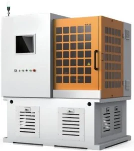
Mainly suitable for automatic balance correction of disc rotors such as flywheels, pulleys, brake drums, gears, clutches, flanges, planetary carriers, differential housings, brake discs, water pump impellers, flanges, and pulleys.
Project Details | DLX30 | DLX42 |
Equipment appearance dimensions | 1700*1250*1970mm | |
Cycle time | ≤ 50s (arc cutting); ≤ 60s (circular drilling) | 60-80s one-time milling (secondary milling not exceeding 2 minutes) |
Workpiece diameter range | Φ180-450mm | Φ250-550mm |
Workpiece quality range | ≤35kg (including tooling) | ≤42kg (including tooling) |
Workpiece height range | ≤200mm | ≤300mm |
Three claw clamping diameter range | Φ180-450mm | Φ250-550mm |
Balance the maximum diameter separately | ≤400mm | |
Maximum milling depth | ≤10mm | |
Balance speed | ≤ 1200rpm (adjustable) | |
Balance correction method | Arc milling/axial drilling/radial drilling | |
Reduction rate of unbalance | URR≥90% | |
Minimum attainable residual imbalance | ≤1g.mm/kg | |
Balance motor power | 2KW (servo motor) | |
Laser engraving machine power | 50W | |
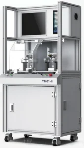
Mainly suitable for testing motor vibration, noise, voltage, current, negative pressure, and other aspects.
Test Function | Project Details | Parameter Range | ||||||
Voltage Test | Measurement parameters | AC/DC voltage | ||||||
Measurement range | 600V | 300V | 100V | |||||
Resolution | 0.1V | 0.1V | 10mV | |||||
Exactitud | ±0.4%F.S±3digit | |||||||
Current Test | Measurement parameters | AC/DC current | ||||||
Measurement range | 20A | 10mA | 5A | 1000mA | 100mA | |||
Resolution | 10mA | 1mA | 1mA | 0.1mA | 0.01mA | |||
Exactitud | ±0.4%F.S±3digit | |||||||
Negative Pressure Test | Measuring range | 0~500g | ||||||
Zero point output | ±0.2% of R.0 | |||||||
Working temperature range | -20℃~60℃ | |||||||
Temperature compensation range | 0℃~40℃ | |||||||
Zero temperature drift | ±0.1% R.0/10℃ | |||||||
Full range temperature drift | ±0.1% LOAD/10℃ | |||||||
Vibration Test | Displacement measurement | 0~1999μm,p-p (10~1kHz BP)(0.00~78.7mil) | ||||||
Speed measurement | 0.0~199.9mm/s,0-p(10~1kHz,IS02954)(0.00~7.87in/sec) | |||||||
Acceleration measurement | 0.00~19.99g,rms(10HzHP) | |||||||
Measurement accuracy | 5%(10~10kHz) | |||||||
Acceleration gauge sensitivity correction | Can input acceleration gauge sensitivity (100mV/g ± 30%) | |||||||
Temperature and Humidity | Operating environment temperature and humidity | -40℃~80℃ / ≤70@RH | ||||||
Noise Test | Sensitivity | 35dB re 1Volt/pasal(18.00mV@94dB SPL) +1/-2dB@1KHz | ||||||
Frequency response | 100Hz~20KHz/3dB | |||||||
Maximum sound pressure level | 130dB@1KHz,1%THD | |||||||
Signal to Noise Ratio | >60dB | |||||||
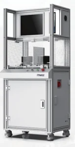
Mainly suitable for overall motor performance testing of DC brushless motors.
Test Function | Project Details | Parameter Range |
Voltage Test | Measurement parameters | AC/DC voltage |
Measurement range | 500V | |
Resolution | 0.1V | |
Exactitud | Level 0.5 | |
Current Test | Measurement parameters | AC/DC current |
Measurement range | 15A | |
Resolution | 0.001A | |
Exactitud | Level 0.5 | |
Negative Pressure Test | Measuring range | -0.1~100MPa |
Pressure type | Gauge pressure (default), absolute pressure | |
Accuracy class | 0.2%FS/0.1%FS | |
Overload capacity | ≤ 1.5 times | |
Mechanical vibration | 20G(20~5KHz) | |
Compensation temperature | -10~70℃ | |
Zero temperature drift Sensitivity temperature drift | 0.5%FS(MAX) | |
Sample time | 20次/秒 20 times/s | |
Long term stability | 0.2%FS/年 0.2%FS/year | |
Vibration testing (1-3 channels, optional) | Sensitivity (20 ± 5 ℃) Maximum lateral sensitivity | 100mV/g / ≤5% |
Measurement range (peak value) | 50g | |
Frequency response (± 5%) | 1~5000Hz | |
Working temperature range Temperature response | -40~150℃ / According to the temperature curve | |
Base isolation | >10 Ω | |
Noise Test | Measurement range | 20~20KHZ |
Exactitud | ±2dB |
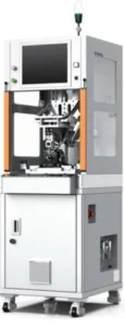
Mainly suitable for vibration testing of motors.
Project Details | Parameter Range |
Equipment appearance dimensions | 800*660*1680mm |
Cycle time | 40s |
Operating Temperature | 0-45℃ |
Measurement frequency range | 0-10kHz |
Measurement accuracy | 5%(10-10KHz) |
Automatic shutdown | Software measurement end signal |
Precision measurement of acceleration | 0.000-1.999g rms |
Precision measurement of displacement | 0-199.9um,p-p |
Precision measurement of speed | 0.00-19.99mm/s 0-P |
Vibration display | Acceleration value and spectral analysis |
Gas source | 0.4-0.5Mpa |
Drive mode | Self driving (customer provided driver board) |
Spectrum analysis function | 1/3 octave spectrum |
Equipment power supply | 220V/50HZ |
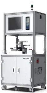
High precision and efficiency: Modular design, compact structure; High sensitivity sensor for precise measurement.
Easy to operate: Independently developed testing software with intuitive interface display and strong operability.
Safe and stable: Independent intellectual property rights, stable equipment performance, and support for highly customized solutions for special products.
Project Details | Parameter Range |
Equipment appearance dimensions | 800*660*1680mm |
Input channel | Six analog acceleration sensors (maximum 10V, 10mA) |
Input parameter | 10-1000Hz total vibration x 6 points |
FFT spectrum analysis | 40kHz,ISO2954 |
Sensor | 100mV/g accelerometer |
Data acquisition card | BV Expert Eight Channel Integration |
safety protection | Organic glass protective door |
Gas source | ≥0.4Mpa |
Equipment power supply | 220V/50HZ |
Mainly suitable for dynamic balance testing of plastic, aluminum alloy fan blades and rotors.
High precision and efficiency: The data acquisition system has strong anti-interference ability, high stability, and accurate measurement; Industrial computer measurement system, with strong universality and easy adjustment.
Easy to operate: Measurement is carried out through servo motor belt transmission, and the operation is simple and easy to understand. The measurement sensor uses an accelerometer as the signal source, which is small in size, has good linearity, is maintenance free, and has a long lifespan.
Project Details | Parameter Range |
Equipment appearance dimensions | 500*450*760mm |
Distance between two supports | 60-320mm |
Roller support journal range | Φ6-25mm |
Workpiece diameter range | Φ20-120mm |
Workpiece quality range | 0.2-3kg |
Reduction rate of unbalance | URR≥95% |
Minimum attainable residual imbalance | ≤0.3g.mm/kg |
Drive mode | Flat belt |
Equipment power supply | 220V/50Hz |
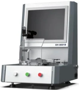
Mainly suitable for overall balancing of high-speed brushless vacuum cleaner motors and DC brushed fans.
High precision and efficiency: Meet the accuracy requirements of G1, with good repeatability and linearity, and ensure smooth operation of the entire machine.
Easy to operate:The same motor and speed do not require repeated calibration; The balance display interface is intuitive, with direct numerical display of the balance machine’s measurement value and angle.
Project Details | Parameter Range |
Equipment appearance dimensions | 470*520*680mm |
Cycle time | ≤25s |
Workpiece diameter range | Φ 30-80mm (size of motor fixing point) |
Balance speed | 3000-80000rpm |
Balance correction method | Scissor cutting |
Balance display accuracy | 0.1mg |
Reduction rate of unbalance | URR≥95% |
Minimum attainable residual imbalance | ≤0.5g.mm/kg |
Drive mode | Self driven |
Equipment power supply | 220V/50Hz |

 Spanish
  English
  Russian