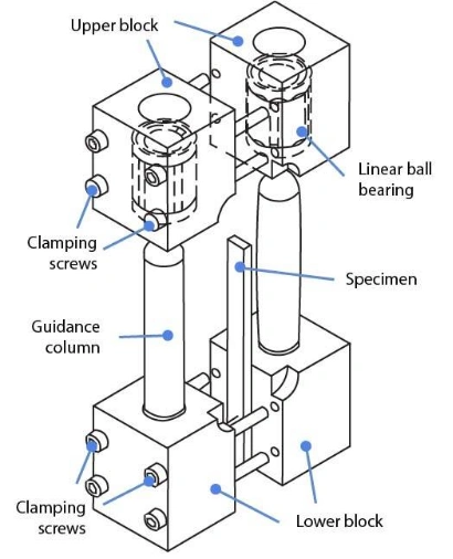
A CLC(Combined Loading Compression ) test fixture is necessary for performing ASTM D6641 testing. The fixture is placed between two compression platens which initiate the compressive force onto the fixture, which in turn subjects the specimen to a combination of Shear- and End-Loading.
Notes:
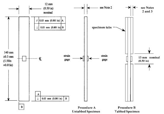
(1) The specimen ends must be parallel to each other within 0.03 mm [0.001 in.] and also perpendicular to the longitudinal axis of the specimen within 0.03 [0.001 in.].
(2) Nominal specimen and tabbing thickness can be varied, but must be uniform. Thickness irregularities (for example, thickness taper or surface imperfections) shall not exceed 0.03 mm [0.001 in.] across the specimen or tab width or 0.06 mm [0.002 in.] along the specimen grip length or tab length.
(3) Tabs are typically square-ended and on the order of 1.6 mm [0.06 in.] thick, but thickness can be varied as required, as discussed in 8.2.
(4) The faces of the specimen may be lapped slightly to remove any local surface imperfections and irregularities, thus providing flatter surfaces for more uniform gripping by the fixture.
- Specimen Installation
Before the test, inspect the test fixture to ensure smooth operation, ensure the clamping and loading surfaces are undamaged, and clean and lubricate the bolts and fixture threads. The specimen installation process should be completed on a granite plate to ensure the specimen end is flush with the fixture base plane.
Operation 1: Remove the upper part of the fixture and place the specimen in the lower part. Gently tighten the four bolts by hand.
Operation 2: Invert the lower part of the fixture and align it with the upper part. Insert the guide pin and slide it into the upper part of the fixture at a uniform speed.
Operation 3: Place the assembled fixture sideways with the threaded side facing up. Tighten the bolts to 3 N·m in three stages using a torque wrench. The fixture and specimen installation are complete.
- Start test
Load the specimen in compression to failure at a nominal rate of 1.3 mm/min [0.05in./min], while recording force, displacement, and strain data. Loading time to failure should be 1 to 10 min. If only modulus is being determined, load the specimen approximately 10 % beyond the upper end of the strain range being used to determine modulus.
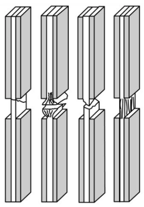
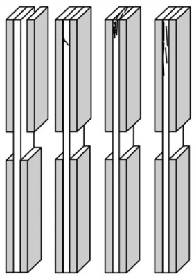
- Analysis of the Validity of Test Results
After the test, inspect the specimens and note the type and location of failure. For a valid test, the final failure of the specimen should occur within the working section, and the ends should not be crushed during the test. At least five specimens should be tested under the same conditions.