Recently, the SCHOOL OF MECHANICAL SCIENCE at Nanjing University of Science and Technology conducted a comprehensive hybrid creep-fatigue interaction HCFI test using the SINOTEST RPL100 Creep-Fatigue Testing Machine (hereinafter referred to as the equipment).
During the test, the RPL100 creep-fatigue testing machine, through its controller, switches the sample’s control mode from strain-controlled fatigue cycles to stress-controlled during unloading after the fatigue cycle. This simulates two load control modes under actual working conditions: the strain-controlled mode during cyclic loading, and the stress-controlled mode during dwell or steady loading (dwell time). It accurately replicates the HCFI hybrid loading mode experienced by high-temperature components in real-world applications.
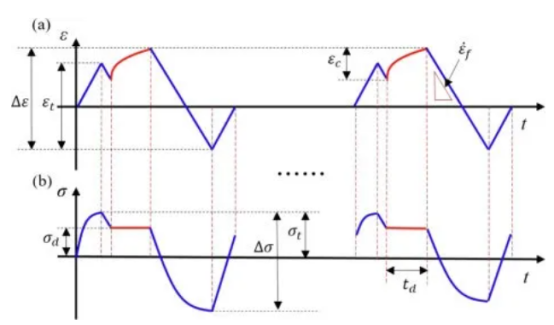
Below figure illustrates stress and strain control conditions at different stages of the machine. The blue line represents the strain-controlled fatigue cycle phase in the HCFI test, while the red line indicates the stress-controlled holding phase. The vertical axis shows the creep strain (ε, Figure a) and stress (δ, Figure b) of the sample, with the horizontal axis representing the test duration.
Next, we share two important test data.
Data 1
The figure below illustrates the variation in peak tensile stress of the specimen with increasing cycle numbers under different dwell times and corresponding stresses. It compares four stress levels: 140MPa (a), 150MPa (b), 160MPa (c), 170MPa (d)) and 3 dwell times: 300 seconds [black line], 600 seconds [red line], 1800 seconds [blue line]) against pure fatigue loading (PF, green line). The x-axis represents HCFI cycle numbers (N), while the y-axis shows the specimen’s maximum tensile stress (MPa).
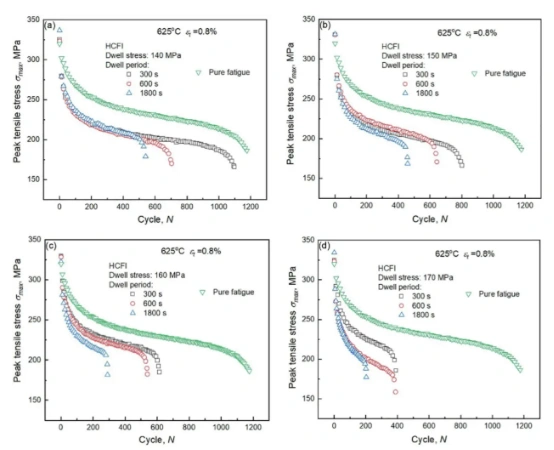
Figure 2: Variation of peak tensile stress in HCFI tests under different dwell times and dwell stresses
The figure demonstrates that when the holding time remains constant, higher stress during the holding period results in a faster increase in the sample’s creep strain. Similarly, under identical holding stress conditions, longer holding time leads to a faster rise in creep strain. Therefore, it can be concluded that in HCFI tests, creep strain increases with both the holding stress and the holding time.
Data 2
The figure below shows the effects of cycle times on creep strain rate under different dwell time stresses (left), and the effects of dwell time stresses on creep strain half-life (right), with traditional creep-fatigue interaction (CCFI) tests for comparison.
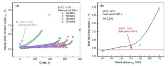
Figure 3: Creep strain responses of HCFI and CCFI tests
The results show that under the same conditions, the increase of residence time stress in HCFI will increase the creep strain velocity of the specimen, but the same effect is not observed in CCFI.
The right figure shows that the creep strain (0.084%) at 140 MPa holding stress in HCFI is comparable to the strain observed in the CCFI test under more extreme conditions (650°C), as indicated by the red line.
This demonstrates that HCFI loads induce greater creep damage than CCFI loads, further confirming that CCFI tests cannot replicate the effects of HCFI on high-temperature components.
The above tests can conclude that the RPL100 creep-fatigue testing machine can fully reproduce the real service environment of high temperature components and complete the mechanical properties test of components under such conditions.
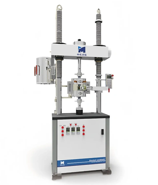
SINOTEST RPL100 Creep-Fatigue Testing Machine
The SINOTEST RPL100 Creep-Fatigue Testing Machine is designed for long-term mechanical property testing of advanced materials and components, including high-temperature alloys, refractory metals, ceramics, and composites. It operates under various extreme conditions such as high-temperature vacuum, inert gas, atmospheric environments, corrosive flue gases, and water-oxygen coupling. The machine covers a comprehensive range of critical performance evaluation items, including creep, long-term strength, stress relaxation, cyclic endurance, creep-fatigue interaction, slow-rate stress corrosion, small-punch creep, and hydrogen embrittlement sensitivity.
The machine employs a high-precision closed-loop control system to enable precise switching between strain control and stress control modes, as well as hybrid loading. This allows for highly accurate simulation of the complex load history experienced by high-temperature components during actual start-stop cycles and steady-state operation. By addressing the limitation of traditional pure strain control tests—where stress relaxation prevents accurate modeling of the stress holding phase—the system successfully reconstructs the creep-fatigue interaction (HCFI) environment under laboratory conditions.
By providing long-term, stable and reliable test data, the RPL100 creep-fatigue testing machine by China Machine Testing breaks the limitation of traditional testing method in simulating real working condition, and unifies the laboratory test condition with the actual service environment of engineering, making the performance evaluation of materials and components more scientific and accurate.
The equipment provides advanced testing solution to break through the technical bottleneck of long life and high reliability design and evaluation of high temperature components, and is an important technical cornerstone to ensure the safe operation of major equipment and enhance the core competitiveness of advanced manufacturing industry.
Appendix: Basic Concept Analysis
① Creep-fatigue interaction: When creep and fatigue damage occur sequentially or simultaneously, one type of damage will have a certain influence on the development process of the other, thus accelerating or slowing down the total damage and affecting the fatigue life of the material. This is called creep-fatigue interaction.
② Stress: Stress refers to the internal forces that interact within an object when it is deformed by external forces.
③Strain: Strain refers to the local relative deformation of an object caused by external forces or non-uniform temperature fields.
④Stress control: The rate of stress increase per unit time.
⑤Strain control: controls the increase of local strain per unit time.
⑥Stress relaxation: Stress relaxation refers to a phenomenon where the total deformation (comprising elastic and plastic deformation) of a component remains constant, while creep causes the plastic deformation to progressively increase and the elastic deformation to decrease correspondingly, with stress gradually decreasing over time.
⑦ Creep: The phenomenon where the strain of a solid material increases over time while the stress remains constant.
⑧ Creep strain: Creep strain refers to the plastic deformation that occurs in materials over time under constant stress.